Soil pollution remediation device

A soil pollution and outer shell technology, applied in the field of soil pollution remediation, can solve the problems of single treatment method, general soil remediation effect, difficult to effectively remediate soil, etc., and achieve the effect of improving the crushing effect and soil fertility.

Inactive Publication Date: 2020-12-11
卢超
View PDF0 Cites 0 Cited by
  • Summary
  • Abstract
  • Description
  • Claims
  • Application Information

AI Technical Summary

Benefits of technology

This technology helps clean up harmful substances that may have been buried underground or left over after construction without causing damage. It uses special tools made of materials like ceramics called photo-lithography (PL) lamps to break down any unwanted material into small pieces before they enter the ground. These tiny fragments help remove impurities such as dirt, rust, grease, oil residue, etc., making them easier to dispose back out properly. Additionally, this method allows for effective removal of certain types of chemicals found within wastewater streams while reducing environmental impact. Overall, these technical benefits aim to provide an improved solution for treating unsanitary areas caused due to accumulation of various compounds containing chlorophyll molecules.

Problems solved by technology

This patented technical problem addressed in this patents relates to improving the efficiency at cleaning contaminated land caused by excessive amounts of harmful materials such as pesticides from industry waste residue that can be transferred through rainwater runoff onto other areas causing environmental damage. Current devices only work well within certain limits due to factors like high concentrations of heavy metals found near these sites. Therefore, new solutions must be developed to efficiently remove unwanted compounds while minimizing negative effects on both environmentally sensitive regions (e.g., fisheries) and human health concerns associated with exposure to them.

Method used


Image

  • Soil pollution remediation device
  • Soil pollution remediation device
  • Soil pollution remediation device

Examples


Embodiment 1

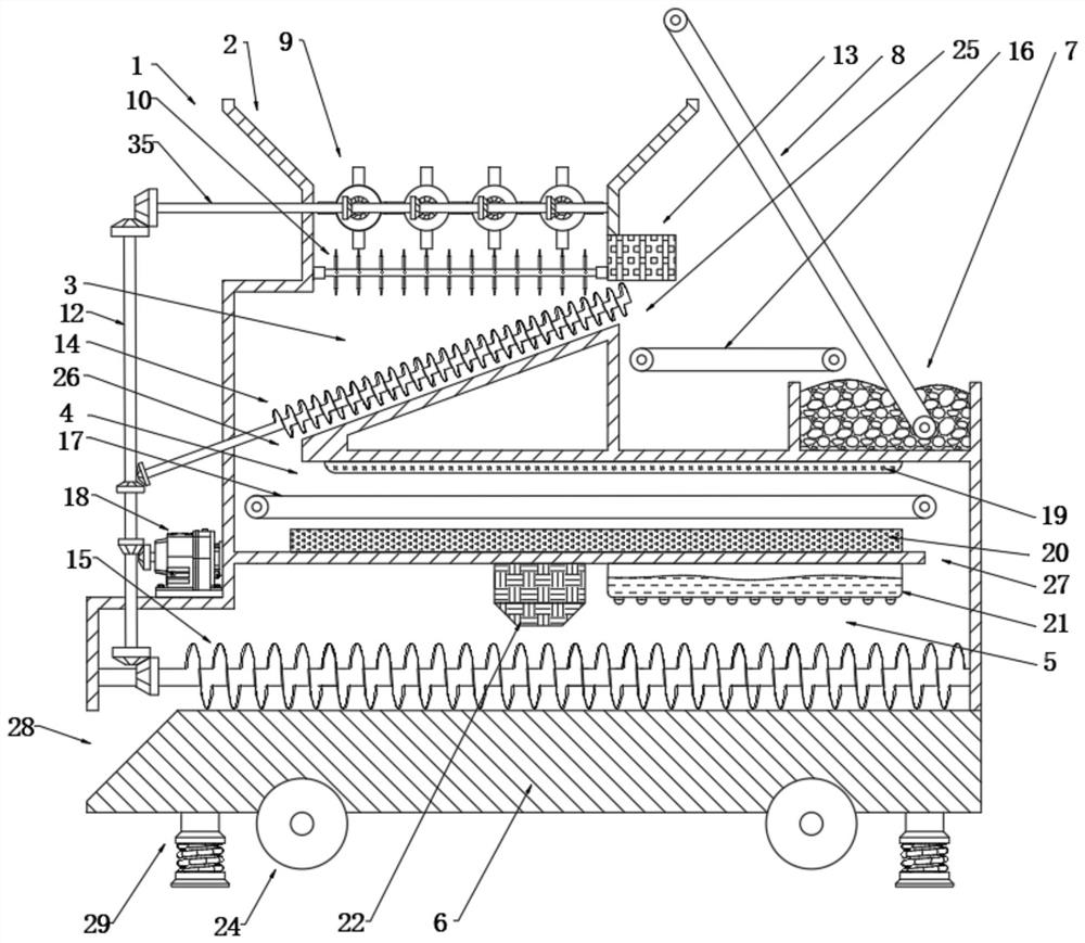
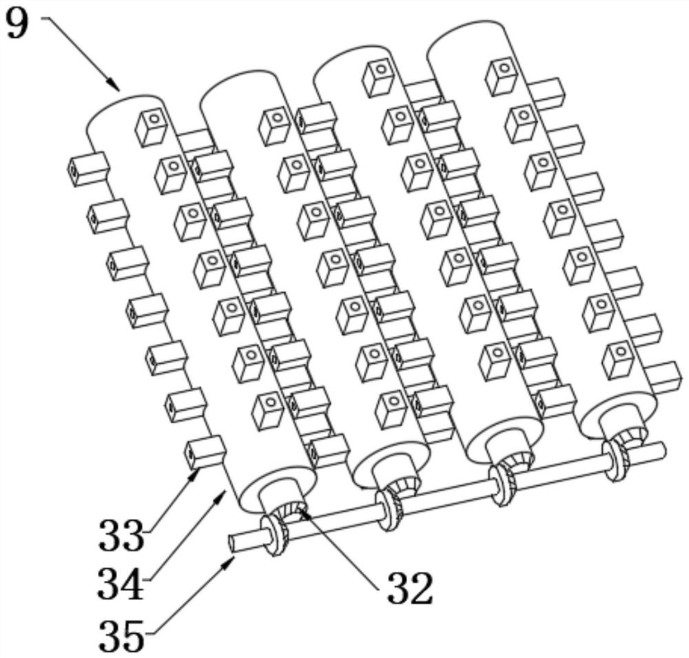
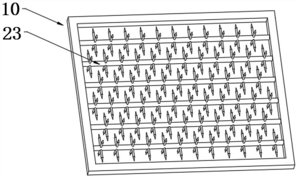
[0026] see Figure 1-5 , a soil pollution remediation device, comprising a base 6 and an outer shell 1 arranged on the base 6, a funnel-shaped opening 2 is arranged above the outer shell 1, and the opening 2 is connected to a separation chamber 3 provided in the outer shell 1 Connected, one side of the outer casing 1 is provided with a feeding pool 7, and a first conveyor belt 8 is provided between the feeding pool 7 and the opening 2, and the contaminated soil placed in the feeding pool 7 can be transported through the first conveyor belt 8 In the opening 2, a crushing mechanism 9 is provided above the separation chamber 3, and the soil entering the separation chamber 3 can be crushed by the crushing mechanism 9. A separation dragon 14 is arranged obliquely in the separation chamber 3, and the separation chamber The bottom surface of 3 is parallel to the separation dragon 14 and there is a certain gap between the bottom surface of the separation chamber 3 and the separation drag

Embodiment 2

[0034] This embodiment is further improved on the basis of Embodiment 1, and the improvement is that: the microbial repair granule 11 includes a microbial layer 38, a nutrient layer 37 and a water-soluble protective layer 36, and the microbial layer 38 is wrapped around the nutrient layer 37 , the nutrient substance layer 37 is wrapped with a water-soluble protective layer 36. When the microbial remediation particles 11 are mixed with the soil with moisture, the water-soluble protective layer 36 melts, so that the microbial layer 38 and the nutrient substance layer 37 are mixed with the soil. The microorganisms contained in the layer 38 degrade the organic pollutants in the soil, while the nutrient substance layer 37 can not only increase the reproduction speed of the microorganisms, but also make the soil more fertile.


PUM


Abstract

The invention discloses a soil pollution remediation device which comprises a base and an outer shell arranged on the base, a funnel-shaped opening is formed in the upper portion of the outer shell, the opening is communicated with a separation cavity formed in the outer shell, a feeding pool is arranged on one side of the outer shell, and a first conveying belt is arranged between the feeding pool and the opening; a crushing mechanism is arranged above the separation cavity, and a separation auger is obliquely arranged in the separation cavity; when the device is used, the first conveying belt conveys contaminated soil placed in the feeding pool into the opening, the smashing mechanism smashes the soil entering the separation cavity, the smashed soil passes through a filter sieve to separate out garbage such as crushed cloth or plastic bags in the soil, the remediation effect of the soil pollution remediation device is improved, and then the soil passing through the separation auger enters the treatment chamber from the inlet of the treatment chamber to perform photolysis treatment and pyrolysis treatment on organic pollutants in the soil.

Description


Claims


Application Information

Patent Timeline
Owner 卢超
Why Eureka
Try Eureka