New energy automobile charging gun with over-high temperature automatic locking protection function

A technology of new energy vehicles and charging guns, which is applied in the direction of electric vehicle charging technology, electric vehicles, charging stations, etc., and can solve problems such as short circuit between socket and plug, heat of the gun head, and lack of temperature protection function

Inactive Publication Date: 2020-12-25
中铁电气化设备(广东)有限公司
View PDF0 Cites 2 Cited by
  • Summary
  • Abstract
  • Description
  • Claims
  • Application Information

AI Technical Summary

Problems solved by technology

[0003] Since the power of the car is relatively large when charging, but the traditional car charging gun does not have a temperature protection function, if the charging gun head part fails during charging, or it is used frequently at a high temperature, it will cause serious damage. To a certain extent, it will cause the head of the gun to heat up, but because there is no temperature detection function, it is impossible to perform power-off processing by itself. The increasing heat accumulation will cause a short circuit between the socket and the plug, which will easily cause damage to the car battery and make the head of the gun. The plastic is deformed by heat and cannot be pulled out. In severe cases, it may even cause a fire. Therefore, we have proposed a charging gun for new energy vehicles that is automatically locked and protected when the temperature is too high.

Method used


Image

  • New energy automobile charging gun with over-high temperature automatic locking protection function
  • New energy automobile charging gun with over-high temperature automatic locking protection function
  • New energy automobile charging gun with over-high temperature automatic locking protection function

Examples


Embodiment Construction

[0025] The following will clearly and completely describe the technical solutions in the embodiments of the present invention with reference to the accompanying drawings in the embodiments of the present invention. Obviously, the described embodiments are only some, not all, embodiments of the present invention. Based on the embodiments of the present invention, all other embodiments obtained by persons of ordinary skill in the art without making creative efforts belong to the protection scope of the present invention.

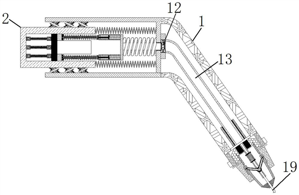
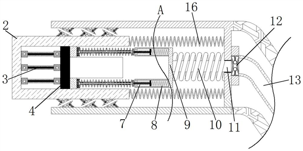
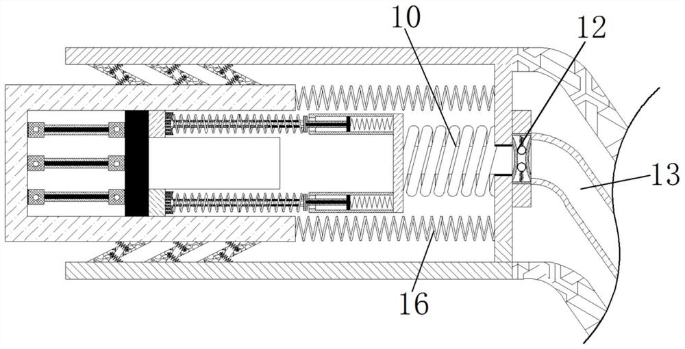
[0026] see Figure 1-7 , a charging gun for new energy vehicles that is automatically locked and protected when the temperature is too high. The outer side of the rod 3 is fixedly connected with a push plate 4, and the end of the push plate 4 away from the thermal rod 3 is fixedly connected with a receiving block 5, and the end of the receiving block 5 away from the push plate 4 is fixedly connected with a connecting spring 6, and the outside of the connecting...


PUM


Abstract

The invention relates to the technical field of new energy charging, and discloses a new energy automobile charging gun with an over-high temperature automatic locking protection function. The new energy automobile charging gun comprises a charging gun main body, wherein a movable block is fixedly connected to the interior of the charging gun main body, a thermal induction rod is arranged in the movable block, a push plate is fixedly connected to the outer side of the thermal induction rod, a bearing block is connected to the end, which is away from the thermal induction rod, of the pushing plate, a connecting spring is fixedly connected to the end, which is away from the pushing plate, of the bearing block, a connecting rod is fixedly connected to the outer side of the connecting spring,a compression spring is movably connected to the outer side of the mounting plate, a clamping block is fixedly connected to the end, which is away from the mounting plate, of the compression spring, and a check valve is fixedly connected to the outer side of the clamping block. According to the new energy automobile charging gun with the over-high temperature automatic locking protection function,through clamping and fixing of the check valve, current transmission cannot be achieved through a current wire connected with the check valve, and the situation that when the temperature is over-high, the current wire still works continuously for charging, and consequently short circuit and fire hazards are caused is avoided.

Description

technical field [0001] The invention relates to the technical field of new energy charging, in particular to a charging gun for new energy vehicles that is automatically locked and protected when the temperature is too high. Background technique [0002] With the improvement of people's living standards, and the current trend of environmental protection, energy saving, and green ecological earth, electric vehicles are developing stronger and stronger with the strong support of the country, and their applications are becoming more and more extensive. The charging guns that match electric vehicles Correspondingly, it has developed rapidly. Electric vehicles are charged through the charging gun cable when charging. The core of the charging gun is the charging gun head connected to the car. [0003] Since the power of the car is relatively large when charging, but the traditional car charging gun does not have a temperature protection function, if the charging gun head part fail...

Claims


Application Information

Patent Timeline
IPC IPC(8): H01R13/508H01R13/56H01R13/713B60L53/16
CPCB60L53/16H01R13/508H01R13/562H01R13/7137H01R2201/26Y02T10/70Y02T10/7072Y02T90/14
Inventor 李立健
Owner 中铁电气化设备(广东)有限公司
Why Eureka
Try Eureka