Calibration device and positioning method for regular geometry

A technology of calibration device and positioning method, applied in the direction of using mechanical device, measuring device, mechanical measuring device, etc., can solve the problems of large displacement of observation point geometry, inaccurate spatial position, etc., to achieve convenient operation, accurate calibration results, and simple structure. Effect

Inactive Publication Date: 2021-01-01
中铁大桥局第七工程有限公司
View PDF6 Cites 1 Cited by
  • Summary
  • Abstract
  • Description
  • Claims
  • Application Information

AI Technical Summary

Benefits of technology

This technology allows us to accurately measure shapes without requiring complicated equipment or tools like scales that may affect their accuracy. It uses specialized devices called calibration machines which attach onto surfaces with specific dimensions and adjust them accordingly based upon these measurements. These instruments have multiple calibration modes where different measurement techniques work together depending on how well they perform correctly. They provide precise data even at high speeds over large areas while still being able to maintain stability during testing.

Problems solved by technology

This technical problem addressed in this patented text relates to accurately measuring spatial locations for multiple types of objects like pipes (hollow) made from materials called HCAP). However, current methods require an extra step involving moving around with tools attached at one end while observing changes over different positions during measurement process. Additionally, there may also exist issues where measurements can affect accuracy when using traditional techniques based only upon binary observations obtained through visual inspection.

Method used


Image

  • Calibration device and positioning method for regular geometry
  • Calibration device and positioning method for regular geometry
  • Calibration device and positioning method for regular geometry

Examples


Embodiment 1

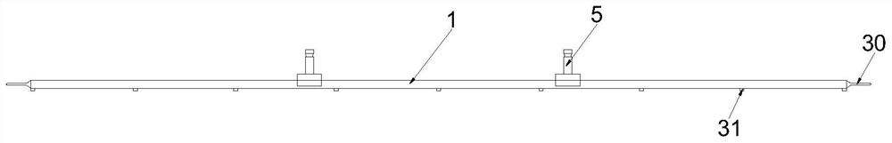
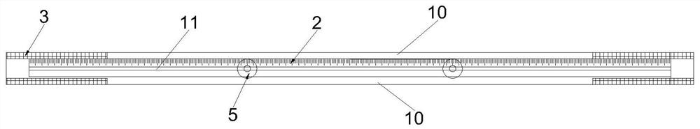
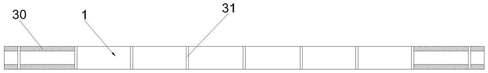
[0046]SeeFigure 1-3 As shown, Embodiment 1 of the present application provides a calibration device for regular geometric bodies, which includes a flexible cover 1, a flexible measuring rule 2, a connecting mechanism 3, and two calibration mechanisms 5. The cover 1 is made of nylon. In order to ensure the bendability of the cover body 1; the measuring ruler 2 adopts 50# first-grade steel strip with a thickness of 0.10mm to ensure the bendability of the measuring ruler 2. The flexible measuring rule 2 is arranged on the cover 1 along the length direction of the cover 1; the connecting mechanism 3 is arranged on the cover 1 and is used to fix the cover 1 on the geometric body 4 to be measured; the calibration mechanism 5 is clamped in The measuring ruler 2 can be moved along the length direction of the measuring ruler 2.

[0047]The calibration device has a use state. When in use, the cover 1 is attached to the outer surface of the test geometry 4 along the circumferential direction of the

Embodiment 2

[0056]Embodiment 2 of the present application provides a positioning method suitable for regular geometric bodies, which includes the following steps:

[0057]S1: Provide the above-mentioned calibration device;

[0058]S2: Fit the cover 1 to the outer surface of the tested geometry 4 along the circumferential direction of the tested geometry 4, and fix the connecting mechanism 3 on the tested geometry 4 to fix the cover 1 and the tested geometry 4 ;

[0059]S3: Move the two calibration mechanisms 5 so that the difference between the scale values ​​of the two calibration mechanisms 5 on the measuring ruler 2 is equal to half of the perimeter of the cross-section of the geometry 4 to be measured. The midpoint is the center of the cross-section of the geometry 4 to be measured, which realizes the calibration of the center of the cross-section of the geometry 4 to be measured;

[0060]S4: Measure the spatial positions of the two calibration mechanisms 5;

[0061]S5: According to the spatial position, the


PUM


Abstract

The invention relates to a calibration device and a positioning method for a regular geometry, and relates to the field of building construction. The calibration device comprises a flexible cover body, a flexible measuring ruler, a connecting mechanism and two calibration mechanisms, and the measuring ruler is arranged on the cover body in the length direction of the cover body; the connecting mechanism is arranged on the cover body and is used for fixing the cover body on a to-be-measured geometry; the calibration mechanism is clamped on the measuring ruler and can move along the length direction of the measuring ruler; in a using state, the cover body is attached to the outer surface of the to-be-measured geometry in the circumferential direction of the to-be-measured geometry, and the connecting mechanism is fixed to the to-be-measured geometry; and a difference value of the scale values of the two calibration mechanisms on the measuring ruler is equal to half of a perimeter of a cross section of the to-be-measured geometry. The calibration device can be fixed to the to-be-measured geometry in an attached mode, the center of the cross section of the to-be-measured geometry can be calibrated through the scale values of the two calibration mechanisms, the structure is simple, operation is convenient, and supports do not need to be erected.

Description


Claims


Application Information

Patent Timeline
Owner 中铁大桥局第七工程有限公司
Why Eureka
Try Eureka