Wheel type conversion feeding and discharging device and numerically-controlled machine tool

A CNC machine tool and wheeled technology, applied in metal processing and other directions, can solve the problems of high labor cost, glass panel preventing position error, unfavorable flexible production, etc., so as to improve the efficiency of loading and unloading, save loading and unloading time, and save labor. cost effect

Pending Publication Date: 2021-02-09
湖南翘楚智能科技有限公司
View PDF0 Cites 3 Cited by
  • Summary
  • Abstract
  • Description
  • Claims
  • Application Information

AI Technical Summary

Benefits of technology

The present in this new design allows an apparatus called loader or Unloader (the machine used during manufacturing) to load and unload material from different parts quickly without having to stop working altogether when changing between them. This saves money compared to traditional methods like manual handling which require stopping work every few hours.

Problems solved by technology

This technical problem addressed in this patents relates to improving the speed and precision of changing over between different types of electronics (LCD) displays without requiring human operators or robotic systems. Additionally, current methods require long hours of assembly/unassembly processes due to their rigid nature.

Method used


Image

  • Wheel type conversion feeding and discharging device and numerically-controlled machine tool
  • Wheel type conversion feeding and discharging device and numerically-controlled machine tool
  • Wheel type conversion feeding and discharging device and numerically-controlled machine tool

Examples


Embodiment 1

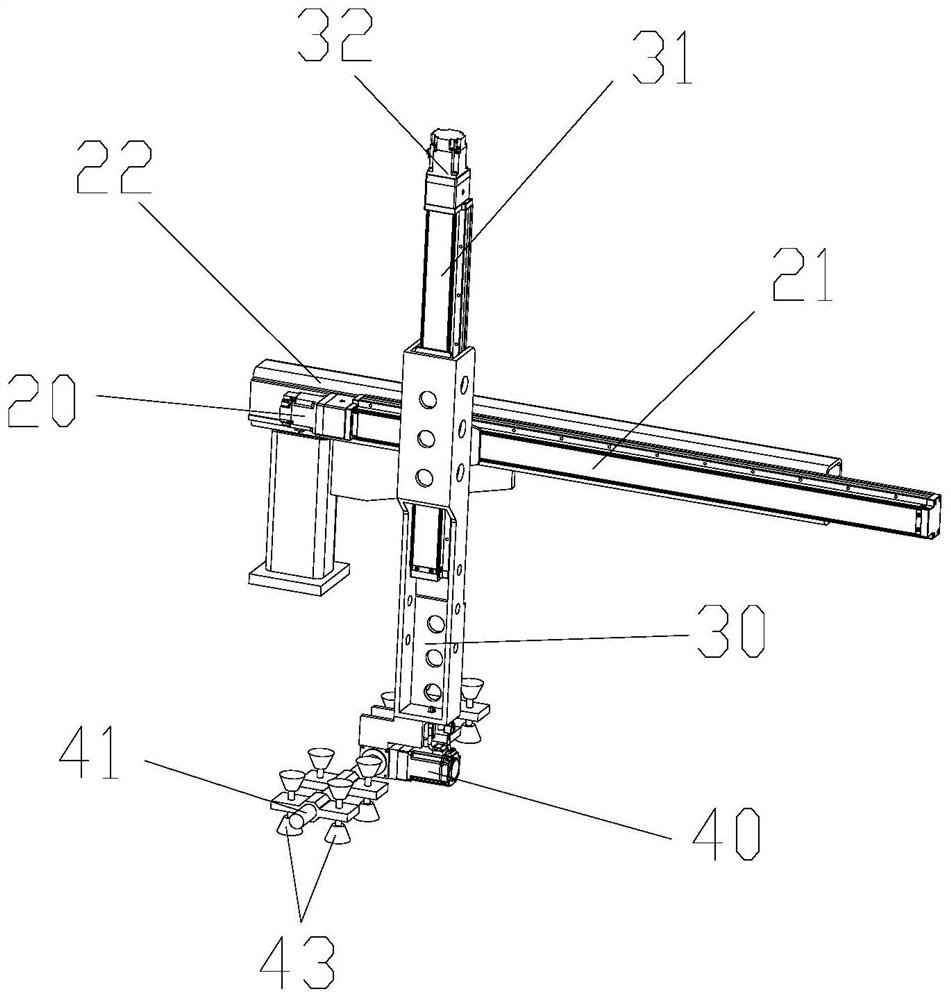
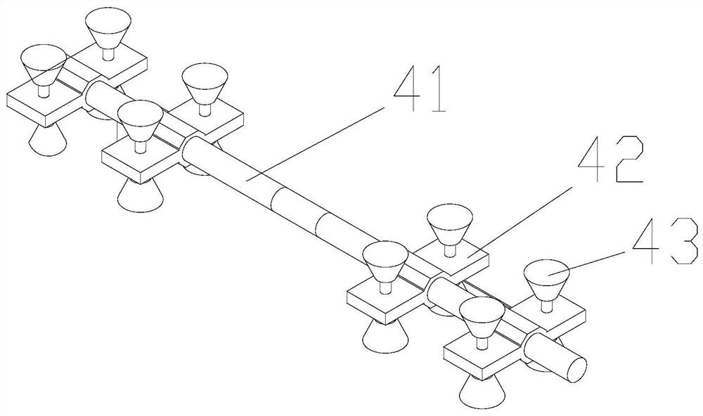
[0038] refer to Figure 1-3 , a wheel-type conversion loading and unloading device, including a crossbeam 12, a reclaiming device, the reclaiming device includes a first moving assembly, a second moving assembly, and a rotating mechanism; the first moving assembly is fixed on the crossbeam 12, and the second moving machine assembly Connected with the first moving assembly, the first moving assembly can be used to drive the second moving assembly to move horizontally; the second moving assembly is connected to the rotating mechanism, and the second moving assembly can drive the rotating mechanism to move vertically; the rotating mechanism includes a rotating Rod 41, material retrieving part 43, retrieving part 43 is fixed on the rotating rod 41, and rotating rod 41 can rotate relative to the second moving assembly; Rotating rod 41 comprises at least two retrieving surfaces, and retrieving part 43 is positioned at the retrieving surface , the pick-up member 43 can be used to pick a

Embodiment 2

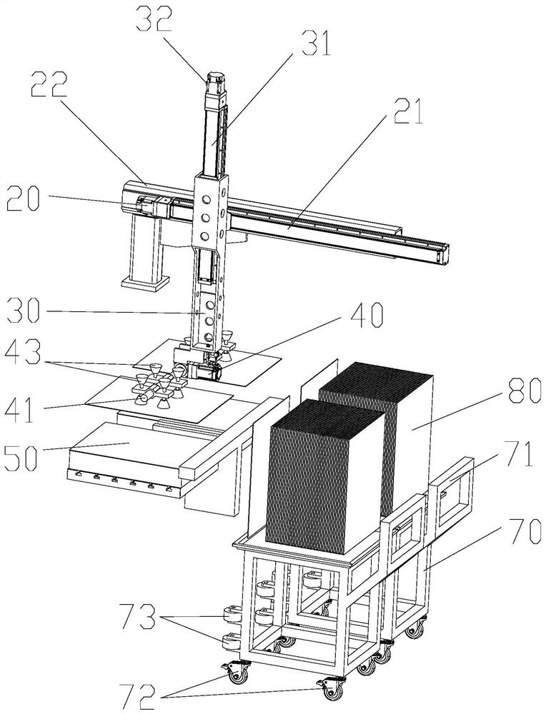
[0044] refer to Figure 1-9 , a kind of numerically controlled machine tool, comprises the wheel type conversion loading and unloading device in embodiment 1, also comprises workbench, processing device, crossbeam 12 is fixed on the workbench, and crossbeam 12 divides workbench into front workbench 10 and rear workbench 11. The wheel-type conversion loading and unloading device is located on one side of the rear workbench 11; the processing device is fixed on the beam 12, and the processing device is located on one side of the front workbench 10, and the processing device is used for processing the material 80.

[0045] Specifically, the workbench is a square structure, the beam 12 spans the workbench, the processing device includes a processing base 50, and the processing base 50 is movably arranged on the workbench through the third moving assembly, and the processing base 50 is used for positioning And fixed material 80. In a specific embodiment, the third moving assembly inc


PUM


Abstract

The invention discloses a wheel type conversion feeding and discharging device, and relates to the field of machine tool machining. The device comprises a cross beam and a material taking device, wherein the material taking device comprises a first moving assembly, a second moving assembly and a rotating mechanism, the first moving assembly is fixed to the cross beam, the second moving assembly isconnected with the first moving assembly, the first moving assembly can be used for driving the second moving assembly to move in the horizontal direction, the second moving assembly is connected with the rotating mechanism and can drive the rotating mechanism to move in the vertical direction, the rotating mechanism comprises a rotating rod and material taking pieces, the material taking piecesare fixed to the rotating rod, the rotating rod can rotate relative to the second moving assembly, the rotating rod comprises at least two material taking faces, and the material taking pieces are located on the material taking faces and used for taking and placing machined materials and/or to-be-machined materials. The wheel type conversion feeding and discharging device is high in working efficiency, seamless combination of material taking and discharging can be achieved by controlling the rotating rod to rotate, feeding and discharging time is saved, the device is suitable for large-scale machining and production, and labor cost is saved.

Description


Claims


Application Information

Patent Timeline
Owner 湖南翘楚智能科技有限公司
Why Eureka
Try Eureka