Middle adapting device for flue gas waste heat recovery

A switching device, flue gas waste heat technology, applied in the direction of heat exchanger type, reducing greenhouse gas, climate sustainability, etc. Advanced problems, to achieve the effect of strong practicability, improved efficiency, and improved heating efficiency

Active Publication Date: 2021-02-12
SHANDONG DAIRONG ENERGY SAVING ENVIRONMENTAL PROTECTION TECH
View PDF7 Cites 0 Cited by
  • Summary
  • Abstract
  • Description
  • Claims
  • Application Information

AI Technical Summary

Problems solved by technology

[0003] However, the traditional flue gas waste heat recovery device cannot fully contact the flue gas with water during use, resulting in slow water heating, resulting in low water heating efficiency, and insufficient recovery of flue gas waste heat

Method used


Image

  • Middle adapting device for flue gas waste heat recovery
  • Middle adapting device for flue gas waste heat recovery
  • Middle adapting device for flue gas waste heat recovery

Examples


Example Embodiment

[0027] The technical solutions in the embodiments of the present invention will be clearly and completely described below with reference to the accompanying drawings in the embodiments of the present invention. Obviously, the described embodiments are only a part of the embodiments of the present invention, but not all of the embodiments. Based on the embodiments of the present invention, all other embodiments obtained by those of ordinary skill in the art without creative efforts shall fall within the protection scope of the present invention.

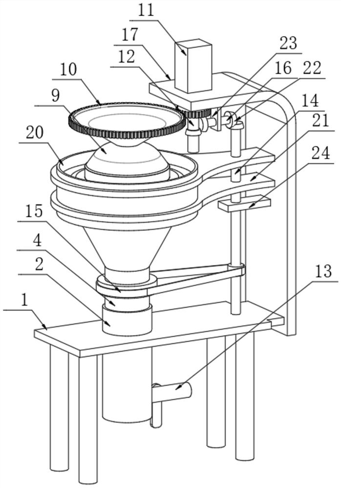
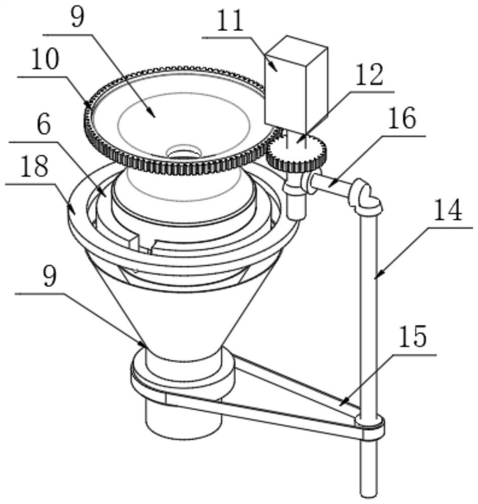
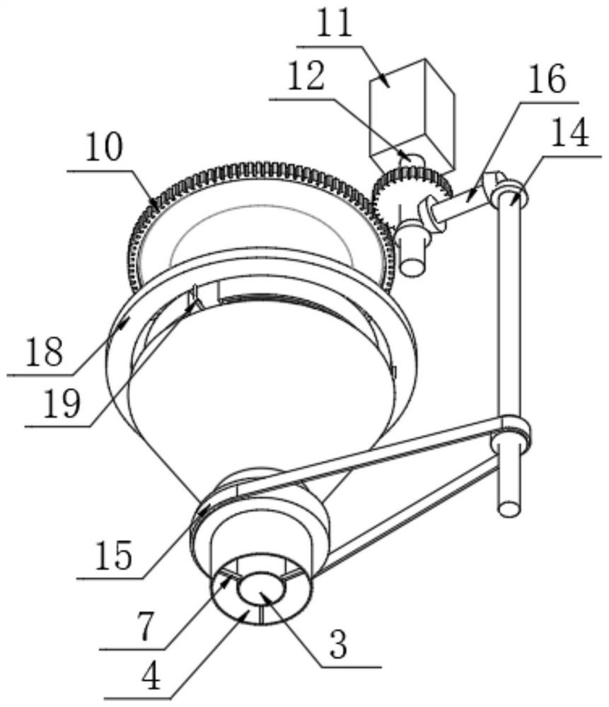
[0028] see Figures 1 to 6 , In the embodiment of the present invention, an intermediate transfer device for waste heat recovery of flue gas includes a platen 1, and a flue gas recovery component is arranged on the top of the platen 1;

[0029] The flue gas recovery assembly includes a connecting pipe 2, an inner pipe 3, an outer pipe 4, a water tank 5 and a deflector 6. The outer pipe 4 is arranged outside the inner pipe 3, and a connec


PUM


Abstract

The invention discloses a middle adapting device for flue gas waste heat recovery and belongs to the technical field of flue gas recovery. The middle adapting device for flue gas waste heat recovery comprises a platen, wherein a flue gas recovery assembly is arranged on the top of the platen. The flue gas recovery assembly comprises a connecting pipe, an inner pipe, an outer pipe, a water tank anda guide plate. The outer pipe is arranged on the outer side of the inner pipe, a connecting rod is fixedly connected between the inner pipe and the outer pipe, the water tank is placed at the top endof the inner pipe, and a drainage groove is formed in the outer side surface of the water tank. According to the middle adapting device for flue gas waste heat recovery, heat is relatively centralized as a lot of flue gas is gathered. When the flue gas is in contact with a water curtain, sliding downward from the inner wall of the outer pipe, with a relatively small water yield, temperature riseof water can be accelerated, so that the water can be heated within a short time. The structure is favorable to prolong the contact time of flue gas and water. The flue gas and the water are in contact fully, so that the water heating efficiency is improved, the flue gas is utilized fully and the device is higher in practicality.

Description


Claims


Application Information

Patent Timeline
Owner SHANDONG DAIRONG ENERGY SAVING ENVIRONMENTAL PROTECTION TECH
Why Eureka
Try Eureka