Photoelectric liquid level sensor

A sensor and opto-hydraulic technology, applied in the field of sensors, can solve the problems of large installation location limitations, large signal interference, short measurement distance, etc., and achieve the effects of accurate and stable detection results, less stray light interference, and reduced loss.

Pending Publication Date: 2021-03-16
XIAMEN HUALIAN ELECTRONICS CO LTD
View PDF14 Cites 5 Cited by
  • Summary
  • Abstract
  • Description
  • Claims
  • Application Information

AI Technical Summary

Benefits of technology

The technical effect of this patented technology allows for longer-distance testing with increased accuracy due to reduced losses from signals being sent through an illumination system that travels along its length inside a cylindrical tube filled with water or other liquids. Additionally, it reduces any unwanted external lights affecting measurements caused by scattered light.

Problems solved by technology

This patented describes two types of liquids levels detection devices - floater and opaque ones. Floating Liquid Level Sensing (FLOS) uses floating objects like balls attached to a rod called a piston to measure their movement within a tank containing fluids. Opacity Layered PhotoElectronic Liquide Semiconductor Liquidesence Detector (OPSD), another device developed by Yokota Technologies Ltd., has been proposed overall due to low cost, reliable operation, longer lifespan, flexibility in mountings options, ease of use, and potential applications in various fields including domestic appliance manufacture, gasoline pipe lines, and airspace safety monitoring.

Method used


Image

  • Photoelectric liquid level sensor
  • Photoelectric liquid level sensor
  • Photoelectric liquid level sensor

Examples


Embodiment Construction

[0032] In order to make the above objects, features and advantages of the present invention more obvious and comprehensible, specific embodiments of the present invention will be clearly and completely described below in conjunction with the accompanying drawings. Apparently, the specific details described below are only some embodiments of the present invention, and the present invention can also be implemented in many other embodiments different from those described here. Based on the embodiments of the present invention, all other embodiments obtained by persons of ordinary skill in the art without making creative efforts belong to the protection scope of the present invention.

[0033] It should be noted that when an element is referred to as being “fixed” to another element, it can be directly on the other element or there can also be an intervening element. When an element is referred to as being "connected to" another element, it can be directly connected to the other elem


PUM


Abstract

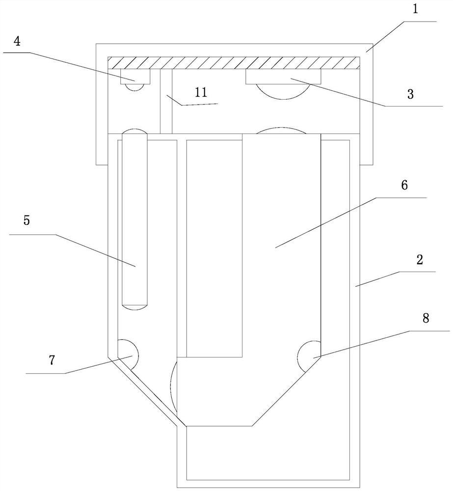
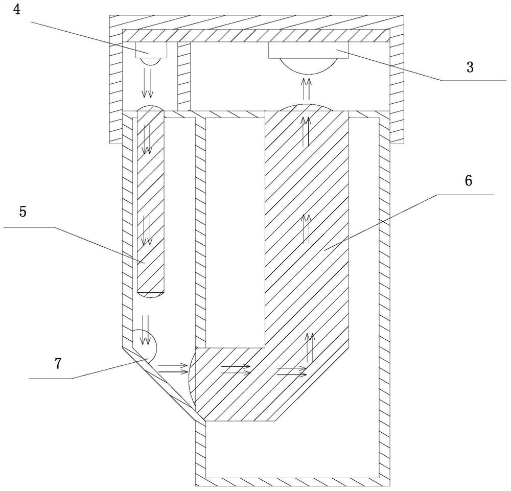
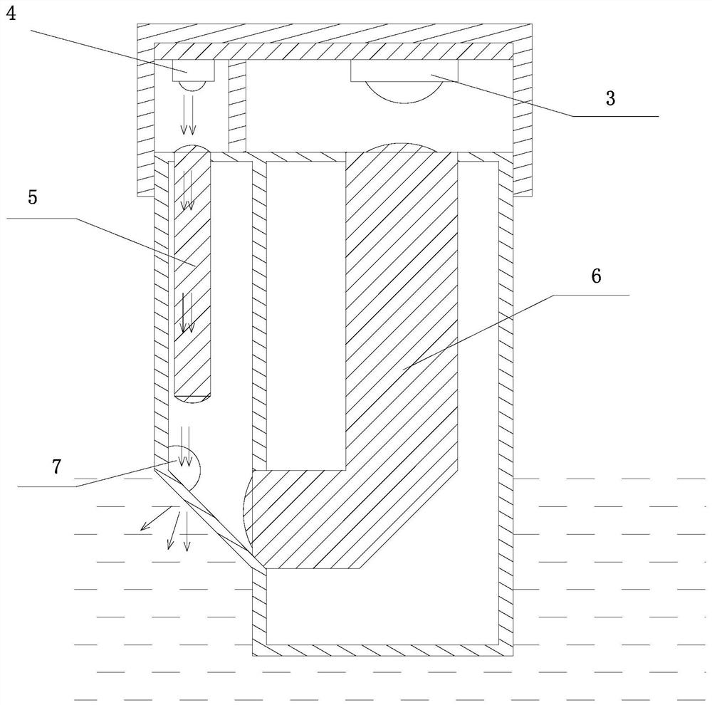
The invention relates to a photoelectric liquid level sensor, which comprises a shell, a photoelectric receiver, a control circuit and at least one group of light guide components, and is characterized in that each light guide component comprises a photoelectric emitter, a first light guide column, a second light guide column and a first reflecting surface; the control circuit is used for controlling the photoelectric emitter to emit signal light and detecting whether the photoelectric receiver receives the signal light or not; the first light guide column guides the signal emitted by the photoelectric emitter to the first reflecting surface; and the first reflecting surface reflects the light guided out by the first light guide column to the second light guide column. And the second lightguide column is made of a transparent light guide material and guides the signal reflected by the first reflecting surface to the position of the photoelectric receiver. According to the invention, as the signal light is transmitted in the light guide column, the loss of the signal light in long-distance transmission can be greatly reduced, the testing distance is greatly increased, and the sensor can be mounted at the top of the liquid container. In addition, stray light interference received by the photoelectric receiver is little, and the detection result is accurate and stable.

Description


Claims


Application Information

Patent Timeline
Owner XIAMEN HUALIAN ELECTRONICS CO LTD
Why Eureka
Try Eureka