Micro-nano drag reduction structure for high-altitude and high-speed environment

An environmental and micro-nano technology, applied in the direction of drag reduction, affecting the air flow passing through the surface of the aircraft, aircraft parts, etc., can solve the problems of complex structure and poor drag reduction effect of the drag reduction device, achieve simple structure and reduce frictional resistance , the effect of increasing the density

Pending Publication Date: 2021-03-26
SHANGHAI INST OF ELECTROMECHANICAL ENG +1
View PDF7 Cites 0 Cited by
  • Summary
  • Abstract
  • Description
  • Claims
  • Application Information

AI Technical Summary

Problems solved by technology

[0005] The inventor believes that the structure of the drag reducing device in the prior art is complicated, the effect of drag reduction is poor, and there is room for improvement

Method used


Image

  • Micro-nano drag reduction structure for high-altitude and high-speed environment
  • Micro-nano drag reduction structure for high-altitude and high-speed environment

Examples


Example Embodiment

[0022] The present invention will be described in detail below with reference to the specific embodiments. The following examples will help to further understand the present invention in any form of technicrat, it will be further understood by those skilled in the art. It should be noted that several variations and improvements can be made without departing from the concept of the present invention without departing from the present invention. These are all of the scope of protection of the present invention.

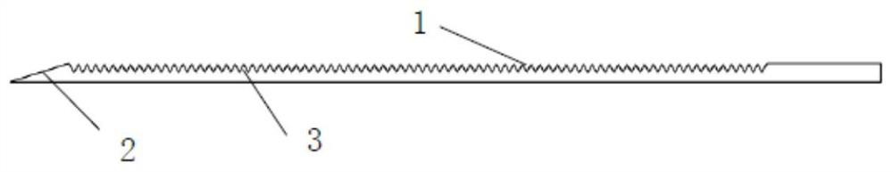
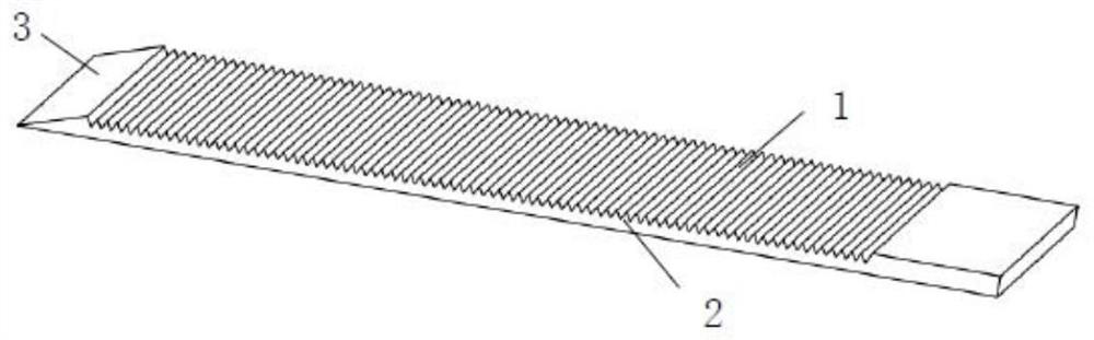
[0023] Such as figure 1 As shown, a microbial reduction structure for a high-altitude high-speed environment provided in accordance with the present invention includes a groove 1 that etchesing the outer surface of the aircraft by laser micronide manufacturing technique, further comprising integrally forming an outer surface of the aircraft. The wind flashes 2, and the air winding surface 2 is located on the wind side of the trench 1. The flight height of the aircraft is high


PUM

PropertyMeasurementUnit
Lengthaaaaaaaaaa

Abstract

The invention provides a micro-nano drag reduction structure for a high-altitude and high-speed environment, which comprises a groove formed in the outer surface of an aircraft, the groove is strip-shaped, the cross section of the groove is an isosceles triangle, the vertex angle of the cross section of the groove is positioned at the bottom of the groove, and the length of the bottom edge of thecross section of the groove is between 150nm and 200nm. The grooves and high-speed airflow form a certain angle, a plurality of grooves are formed in the outer surface of the aircraft in the directionperpendicular to the length direction of the grooves at equal intervals, a partition strip is formed between any two adjacent grooves, the length direction of each partition strip is parallel to thelength direction of the corresponding groove, and the cross section of each partition strip is in an isosceles triangle shape. The vertex angle of the cross section of the dividing strip is located atthe top end of the dividing strip. The viscous resistance near the boundary layer of the near-wall surface can be reduced, the frictional resistance of high-speed gas to the aircraft can be reduced,the structure is simple, the work is reliable, and the drag reduction effect is good.

Description


Claims


Application Information

Patent Timeline
Owner SHANGHAI INST OF ELECTROMECHANICAL ENG
Why Eureka
Try Eureka