Orthopedic surgery traction bed

An orthopaedic surgery, traction bed technology, applied in the directions of surgery, operating table, hospital bed, etc., can solve the problems of labor-intensive, difficult operation, complicated operation, etc., achieve the effect of simple use method, reduce fatigue and discomfort, and reduce the possibility of pollution

Pending Publication Date: 2021-03-30
XI AN JIAOTONG UNIV
View PDF0 Cites 0 Cited by
  • Summary
  • Abstract
  • Description
  • Claims
  • Application Information

AI Technical Summary

Benefits of technology

This new technology allows for easy control over movement during medical procedures without having physical contact between them or requiring anesthesia. It uses two springs - one on each side – that move along different directions when compressed air flows through it. These movements help keep everything moving smoothly while still being able to perform its function effectively.

Problems solved by technology

This technical problem addressed in this patents relates to improving medical procedures involving low level bone fracturing caused by physical force or injury such as falls from high altitude platforms like aircraft or space vehicles. Current methods involve manual lifting techniques that require excess effort and risk exposure to healthcare workers. There have been attempts made towards developing an improved method called closed intramuscular nailsings, but these new ways still suffer issues including complex installation process, potential contaminating materials, difficulty in manipulation, poor visibility when operating through X ray fluoroscopy, and difficulties associated with elevated body weight.

Method used


Image

  • Orthopedic surgery traction bed
  • Orthopedic surgery traction bed
  • Orthopedic surgery traction bed

Examples


Embodiment Construction

[0038] The present invention will be further described in detail below in conjunction with specific embodiments, which are explanations of the present invention rather than limitations.

[0039] The "proximal end" mentioned in the embodiment of the present invention refers to the end close to the operating bed, and the "distal end" refers to the end far away from the operating bed.

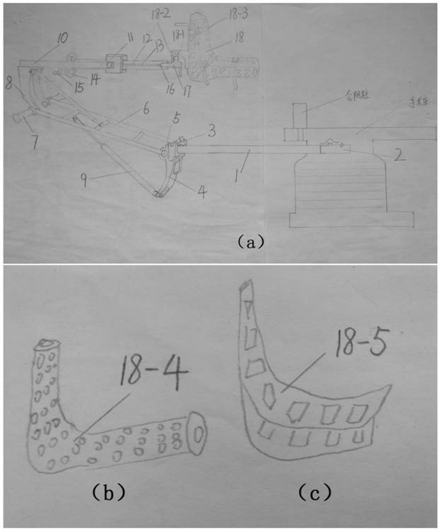
[0040] The traction bed of the present invention comprises a vertical bar 1 , a traction frame 6 , an outreach arm 10 , a through block 11 , a first controllable gas spring 9 , a second controllable gas spring 20 and a traction shoe 18 .

[0041] Such as figure 1 As shown, in use, the vertical bar is parallel to the long axis of the operating table. The proximal end of the vertical bar 1 is fixedly connected to the connecting block 2 of the operating bed, and the connecting block 2 of the operating bed is used to connect with the operating bed. Link to each other; draw frame 6 links to each other wi


PUM


Abstract

The invention provides an orthopedic surgery traction bed, which is characterized in that a vertical rod is connected with a surgical bed, the vertical rod is connected with a traction frame through afirst controllable air spring, the traction frame is connected with an extending arm through a second controllable air spring, the extending arm is connected with a penetrating block, a long nut anda guide plate are arranged in the penetrating block, and a screw is arranged in the long nut, while in use, traction can be implemented by rotating the screw, lifting is controlled through the first controllable air spring, abduction and adduction are controlled through the second controllable air spring, internal and external rotation of the lower limbs is controlled through the rotating guide plate, and therefore free regulation and control of resetting, lifting, abduction and adduction are completed, time and labor are saved, operation is convenient, intraoperative fluoroscopy is not affected, and the possibility of surgical incision pollution is reduced.

Description


Claims


Application Information

Patent Timeline
Owner XI AN JIAOTONG UNIV
Why Eureka
Try Eureka