End conveying device for transfer film

A technology of conveying device and transfer film, which is applied in the directions of transportation and packaging, sending objects, winding strips, etc., can solve the problems of increased cost, many leftover materials, and the transfer film cannot be fully utilized, and achieves the effect of high utilization rate.

Pending Publication Date: 2021-04-02
海盐三湾塑业有限公司
View PDF0 Cites 2 Cited by
  • Summary
  • Abstract
  • Description
  • Claims
  • Application Information

AI Technical Summary

Problems solved by technology

This cutting method has a lot of leftovers, and the transfer film c

Method used


Image

  • End conveying device for transfer film
  • End conveying device for transfer film
  • End conveying device for transfer film

Examples


Embodiment Construction

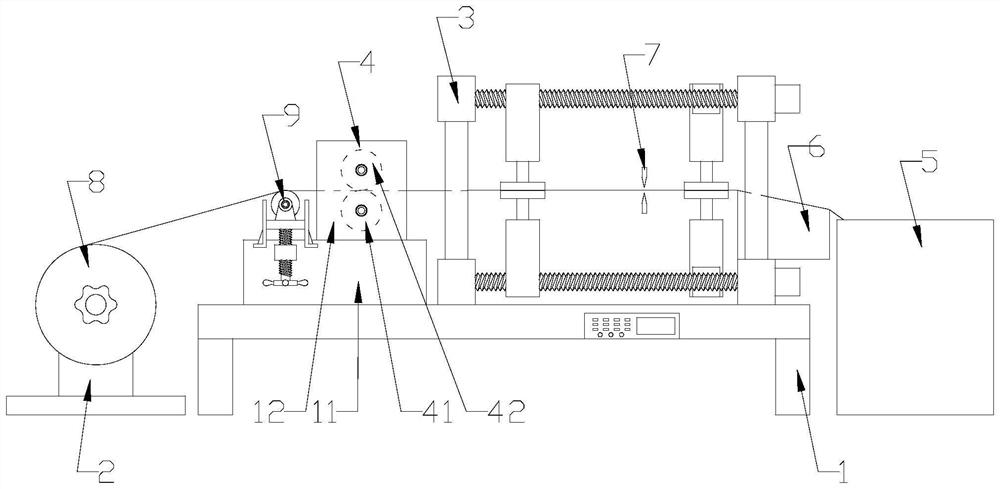
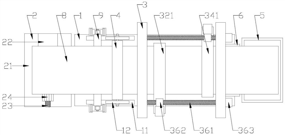
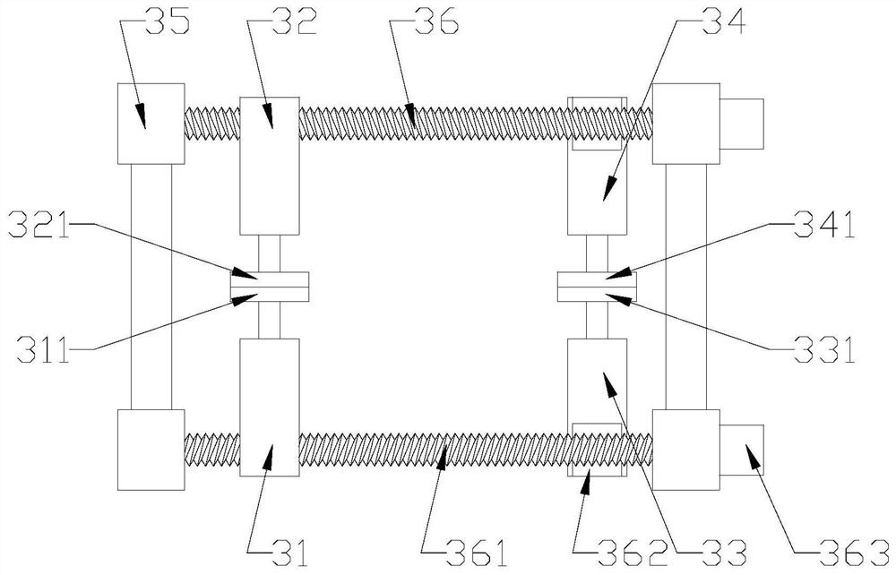
[0018] refer to Figure 1 to Figure 4 , a transfer film end conveying device according to the present invention, comprising a frame 1, a coil rack 2, a conveyor 3, a guide roller set 4, a receiving box 5 and a controller, the coil rack 2 and the receiving Material box 5 is respectively positioned at the left and right sides of frame 1, and described conveyer 3 comprises first air cylinder 31, second air cylinder 32, the 3rd air cylinder 33, the 4th air cylinder 34, conveying frame 35 and conveying driver 36, described The guide roller group 4 and the conveying frame 35 are respectively fixed on the left and right sides of the top surface of the frame 1, and the first cylinder 31 and the third cylinder 33 are respectively fixed on the front and rear sides of the bottom of the conveying frame 35. On the delivery driver 36, the second cylinder 32 and the fourth cylinder 34 are respectively fixed on the delivery driver 36 positioned at the front and rear sides of the top of the deliv


PUM


Abstract

The invention discloses an end conveying device for a transfer film. The end conveying device comprises a rack, a material roll frame, a conveyor, a material guide roller set, a material receiving boxand a controller, the conveyor comprises a first air cylinder, a second air cylinder, a third air cylinder, a fourth air cylinder, a conveying rack and conveying drivers, and the material guide roller set and the conveying rack are fixed to the left side and the right side of the top face of the rack correspondingly. The first air cylinder and the third air cylinder are fixed to the conveying drivers located on the front side and the rear side of the bottom end of the conveying rack correspondingly, and the second air cylinder and the fourth air cylinder are fixed to the conveying drivers located on the front side and the rear side of the top end of the conveying rack correspondingly. A first pressing plate, a second pressing plate, a third pressing plate and a fourth pressing plate are fixed to the ends of telescopic rods of the first air cylinder, the second air cylinder, the third air cylinder and the fourth air cylinder separately, the controller is electrically connected with theconveyor and can be matched with a cutter, the utilization rate of transfer film rolls is effectively increased, and almost no leftover materials exist.

Description


Claims


Application Information

Patent Timeline
Owner 海盐三湾塑业有限公司
Why Eureka
Try Eureka