Tool holder module and machine tool

A tool holder and machine tool technology, used in tool holder accessories, metal processing mechanical parts, turning equipment, etc., can solve the problems of uncontrollable precision, long time consumption, etc., and achieve convenient operation, high degree of automation, and high centering adjustment accuracy. Effect

Pending Publication Date: 2021-04-09
GUANGZHOU ROVMA AUTO PARTS
View PDF0 Cites 0 Cited by
  • Summary
  • Abstract
  • Description
  • Claims
  • Application Information

AI Technical Summary

Benefits of technology

This patented describes an improved mechanism for holding tools used with machining equipment that allows it to center itself accurately on different parts being worked together during manufacturing processes without requiring manual labor. It also makes it easier to use these tools more efficiently by allowing them to automatically move around within specific areas while still maintain their position relative to other components.

Problems solved by technology

This patented describes an apparatus called a triple-jat chip holder where two triangular chucks hold a working plate securely together during millings. However, this design may have issues such as low center alignment precision due to variations caused by manufacturing tolerances and assembly errors. Therefore, technical problem addressed through researchers' analysis needs involves improving the positioning accuracy of these chains while minimizing any potential sources of error.

Method used


Image

  • Tool holder module and machine tool
  • Tool holder module and machine tool
  • Tool holder module and machine tool

Examples


Embodiment Construction

[0038] The following will clearly and completely describe the technical solutions in the embodiments of the present invention with reference to the accompanying drawings in the embodiments of the present invention. Obviously, the described embodiments are only some, not all, embodiments of the present invention. Based on the embodiments of the present invention, all other embodiments obtained by persons of ordinary skill in the art without creative efforts fall within the protection scope of the present invention.

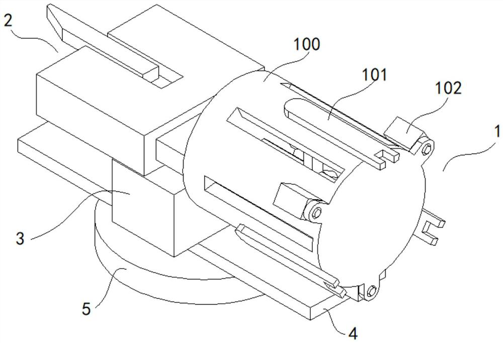
[0039] figure 2 A schematic diagram of the three-dimensional structure of the tool holder module according to the embodiment of the present invention is shown.

[0040] The embodiment of the present invention provides a tool holder module, which includes a tool holder assembly 2 and an adjustment assembly 1 .

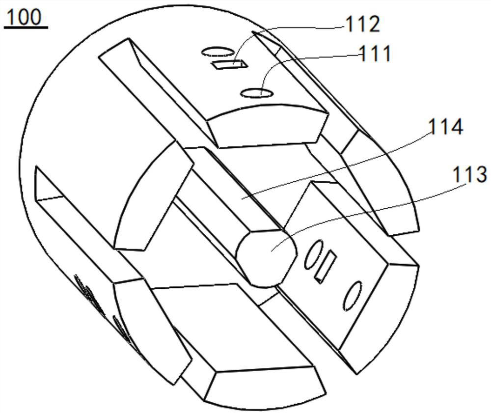
[0041] image 3 A schematic diagram showing the three-dimensional structure of the adjusting frame according to the embodiment of the present invention, F


PUM


Abstract

The invention discloses a tool holder module. The tool holder module comprises a tool holder assembly and also comprises an adjusting assembly, wherein the adjusting assembly comprises an adjusting frame, a plurality of following connecting pieces and multiple groups of adjusting units, wherein a sensing column is arranged on the axis of the adjusting frame; a plurality of pressure sensors are arranged on the outer wall of the sensing column in the circumferential direction; the plurality of following connecting pieces are uniformly arranged in the circumferential direction of the axis; any one of the plurality of following connecting pieces only has the translational degrees of freedom being facing or away from motion of the axis; elastic units are arranged on the plurality of following connecting pieces in the direction being facing the axis; each of the elastic units comprises an elastic piece and a contact piece; the contact pieces are arranged on the following connecting pieces based on the elastic pieces; in a motion process of the following connecting pieces, the contact pieces keep contact with the sensing column; and any one of the multiple groups of adjusting units comprises a driving element. The tool holder assembly has the advantages of being high in automation degree, high in centering adjustment accuracy and the like.

Description


Claims


Application Information

Patent Timeline
Owner GUANGZHOU ROVMA AUTO PARTS
Why Eureka
Try Eureka