High-rotating-speed and high-temperature dryer sealing piece

A high-temperature dry, high-speed technology, applied to the sealing of the engine, engine components, mechanical equipment, etc., can solve the problems affecting the sealing effect, and achieve the effects of prolonging the working life, stabilizing the temperature and facilitating installation

Pending Publication Date: 2021-04-20
ANHUI UNIVERSITY OF TECHNOLOGY AND SCIENCE
View PDF6 Cites 0 Cited by
  • Summary
  • Abstract
  • Description
  • Claims
  • Application Information

AI Technical Summary

Problems solved by technology

[0005] The purpose of the present invention is to provide a high-speed high-temperature dryer seal to solve the problem that the cont

Method used


Image

  • High-rotating-speed and high-temperature dryer sealing piece
  • High-rotating-speed and high-temperature dryer sealing piece
  • High-rotating-speed and high-temperature dryer sealing piece

Examples


Example Embodiment

[0026] The following will clearly and completely describe the technical solutions in the embodiments of the present invention with reference to the accompanying drawings in the embodiments of the present invention. Obviously, the described embodiments are only some, not all, embodiments of the present invention. Based on the embodiments of the present invention, all other embodiments obtained by persons of ordinary skill in the art without making creative efforts belong to the protection scope of the present invention.

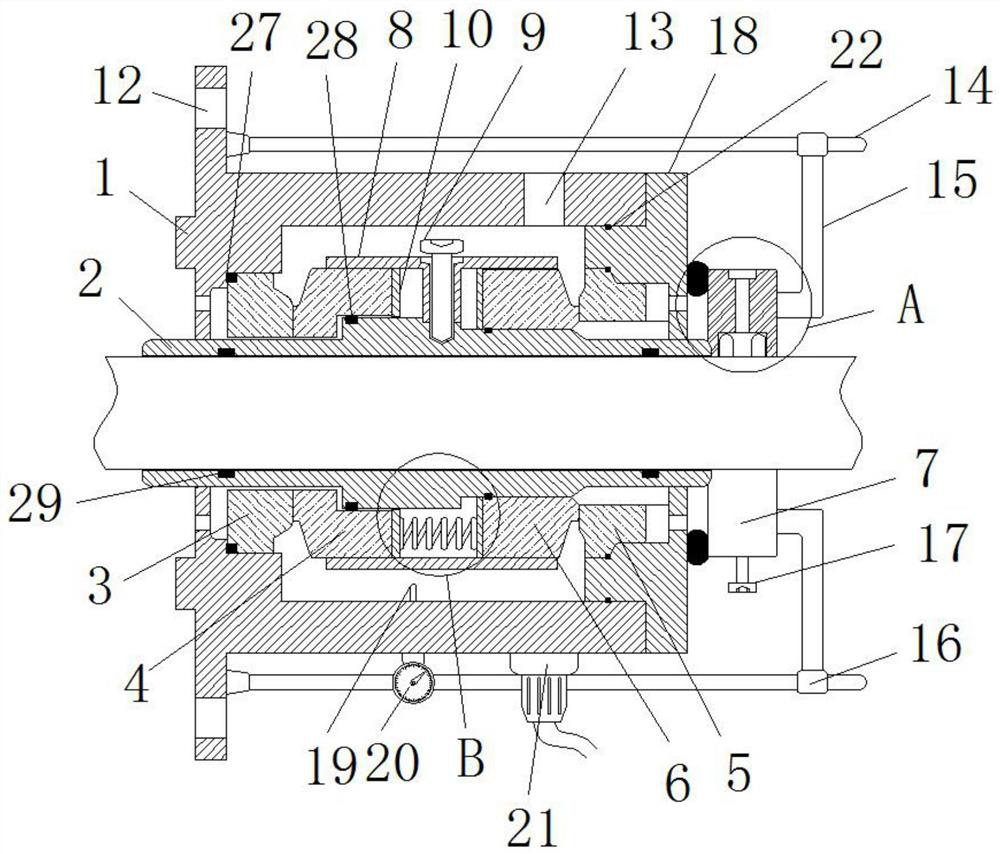
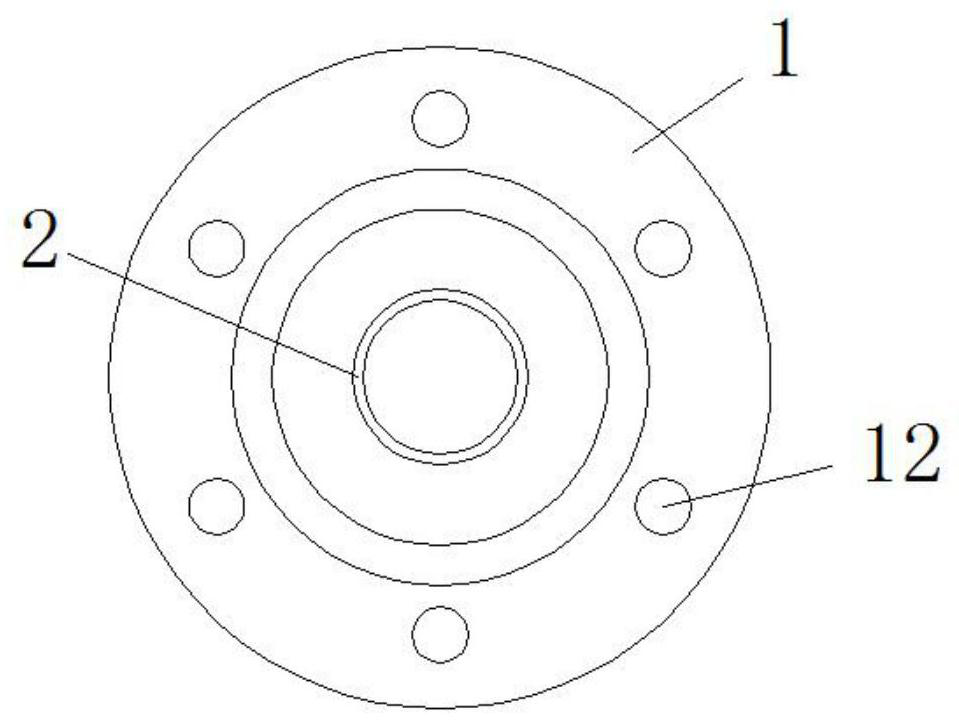
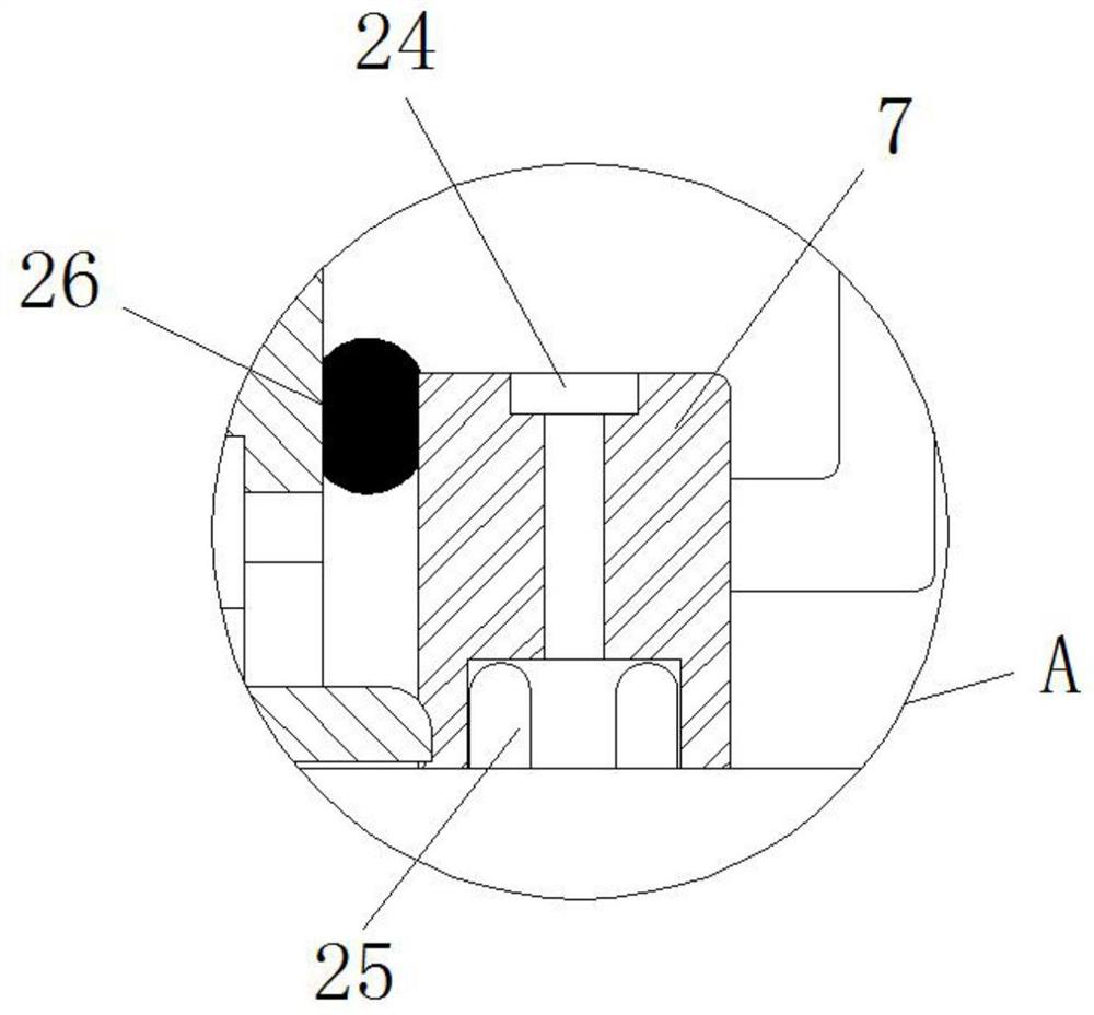
[0027] see Figure 1-6 , the present invention provides a technical solution: a high-speed high-temperature dryer seal, including an end gland 1, a spring envelope 8, a thermometer 20, a one-way valve 21 and a positioning ring 26, and a shaft sleeve is installed inside the end gland 1 2. A shaft sleeve O-ring 29 is installed on the inner side of the shaft sleeve 2, and an installation hole 12 is opened on the end gland 1, and a slide rod 14 is installed on the en


PUM


Abstract

The invention discloses a high-rotating-speed and high-temperature dryer sealing piece. The high-rotating-speed and high-temperature dryer sealing piece comprises an end gland, a spring sealing sleeve, a thermometer, a one-way valve and a positioning ring, wherein a shaft sleeve is mounted on the inner side of the end gland, a shaft sleeve O-shaped ring is mounted on the inner side of the shaft sleeve, a mounting hole is formed in the end gland, and a sliding rod is mounted on the end gland; an extending rod is installed on the sliding rod through a limiting lantern ring, one end of the extending rod is connected with a positioning sleeve, a fastening threaded hole is formed in the positioning sleeve, a fastening bolt is installed in the fastening threaded hole, and a double-layer sealing ring is installed on the inner side of the fastening threaded hole; and the positioning ring is arranged on one side of the positioning sleeve. The high-rotating-speed and high-temperature dryer sealing piece is provided with a static ring O-shaped ring, a movable ring O-shaped ring, the shaft sleeve O-shaped ring and an atmosphere end sealing ring, loss caused by contact and mutual friction between connecting pieces is avoided, the service life of the sealing piece is prolonged, and the sealing effect of long-time use is guaranteed.

Description


Claims


Application Information

Patent Timeline
Owner ANHUI UNIVERSITY OF TECHNOLOGY AND SCIENCE
Why Eureka
Try Eureka