Manufacturing method of blast furnace cooling wall

A manufacturing method and technology of cooling wall, applied in the field of metallurgical equipment, can solve the problems of high manufacturing cost and overall bulky cooling wall, and achieve the effect of reducing volume and weight and reducing manufacturing cost

Pending Publication Date: 2021-05-28
HEBEI WANFENG METALLURGICAL SPARE PARTS CO LTD
View PDF11 Cites 0 Cited by
  • Summary
  • Abstract
  • Description
  • Claims
  • Application Information

AI Technical Summary

Problems solved by technology

[0004] The purpose of the present invention is to provide a method for manufacturing a blast furnace stave, aiming at solving the technical problems that the existing blast furnace stave is bulky and the manufacturing cost is high in order to achieve the cooling effect

Method used


Image

  • Manufacturing method of blast furnace cooling wall
  • Manufacturing method of blast furnace cooling wall
  • Manufacturing method of blast furnace cooling wall

Examples


Example Embodiment

[0041]In order to make the technical problems, technical solutions and beneficial effects to be solved by the present invention, the present invention will be described in further detail below with reference to the accompanying drawings and examples. It should be understood that the specific embodiments described herein are merely intended to illustrate the invention and are not intended to limit the invention.

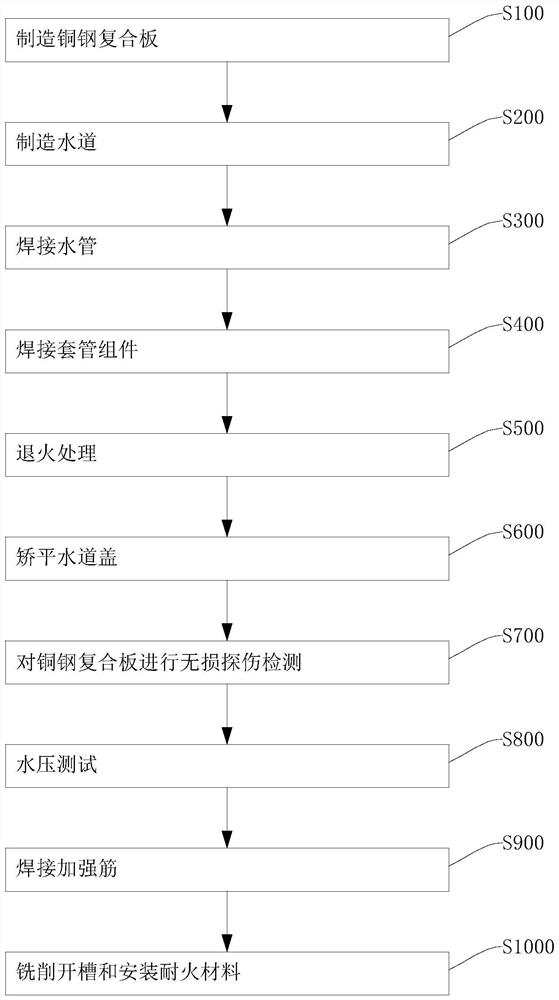
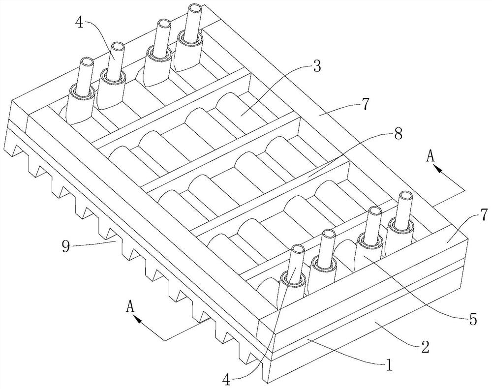
[0042]SeeFigure 1 to 4 The method of manufacturing a blast furnace cooling wall provided by the present invention will now be described.figure 1 A implementation process of a manufacturing method of a blast furnace cooling wall provided in accordance with an embodiment of the present invention is shown, and the process is detailed as follows:

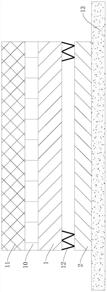
[0043]In step S100, the manufacturing copper steel composite panel is performed, mainly including obtaining the steel sheet 1 and the copper plate 2, by connecting the steel sheet 1 to the copper plate 2 to obtain a copper steel composite pan


PUM


Abstract

The invention provides a manufacturing method of a blast furnace cooling wall, and belongs to the technical field of metallurgical equipment. The manufacturing method of the blast furnace cooling wall comprises the steps of copper-steel composite plate manufacturing, water channel manufacturing and water pressure testing. According to the manufacturing method of the blast furnace cooling wall, a water channel cover welded to a steel plate and a water tank formed in one side of the steel plate jointly define a water channel, the water channel cover is arranged to be a convex cover body, the water passing sectional area of the water channel is increased under the condition that the thicknesses of the steel plate and a copper plate are not excessively increased, and therefore the blast furnace cooling wall achieves a preset cooling effect, the size and the weight of the blast furnace cooling wall are reduced, and the manufacturing cost is reduced.

Description


Claims


Application Information

Patent Timeline
Owner HEBEI WANFENG METALLURGICAL SPARE PARTS CO LTD
Why Eureka
Try Eureka