Motor

A technology of motors and terminals, applied in the direction of electromechanical devices, structural connections, casings/covers/supports, etc., can solve complex problems

Pending Publication Date: 2021-05-28
MINEBEA CO LTD
View PDF1 Cites 2 Cited by
  • Summary
  • Abstract
  • Description
  • Claims
  • Application Information

AI Technical Summary

Benefits of technology

The technical effect of this patented technology allows for creating a device that can be attached to any part or equipment on a circuit without being limited by its own battery source. This makes it easier to use electronics devices with batteries instead of relying solely upon their mains connection.

Problems solved by technology

This patented technical problem addressed by this patents describes how electronic parts like circuits can be protected from excessive heat caused by an electrical current flow when they're used at high voltages or currents for long periods without causing damage.

Method used


Image

  • Motor
  • Motor
  • Motor

Examples


no. 1 approach

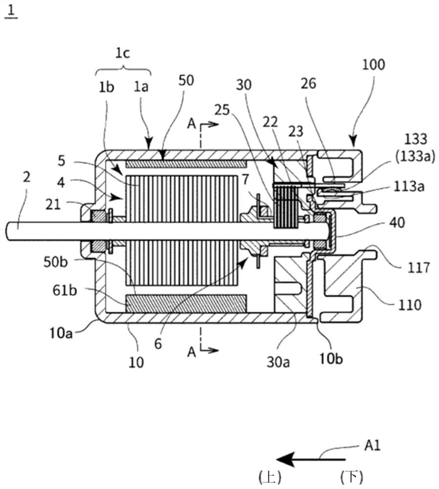
[0031] figure 1 It is a sectional view showing a motor using the terminal unit according to the first embodiment of the present invention.

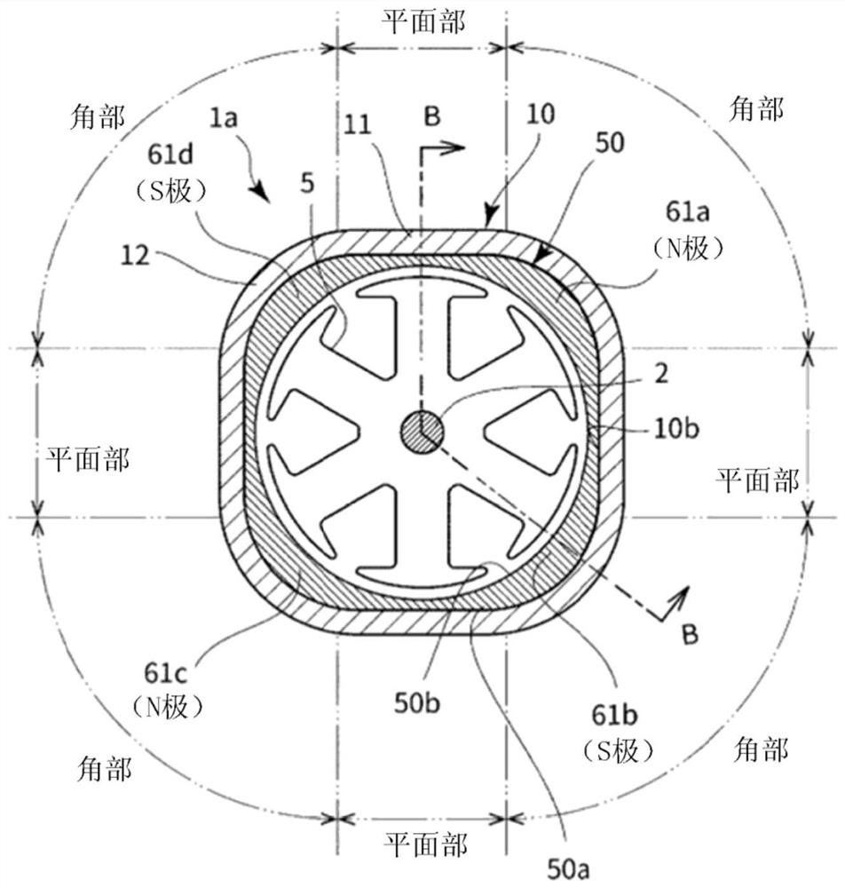
[0032] figure 1 The section shown is that of the following figure 2 The cross-section shown as line B-B in . In the following figures, arrow A1 indicates the direction of the rotation axis. In the arrow A1, the direction of the arrow tip is upward.

[0033] The motor 1 is, for example, a DC motor. The motor 1 generally includes a motor body 1 c and a terminal unit 100 . The motor main body 1c has a frame assembly 1a and a rotor rotatable with respect to the frame assembly 1a. The rotor is composed of a rotating shaft (shaft) 2 and an armature assembly 1b. The terminal unit 100 is attached to, for example, the bottom portion (lower portion) of the motor main body 1c and used.

[0034] The armature assembly 1b is attached to the rotary shaft 2 and has an armature portion 4, a commutator portion 6, and the like. The armature unit 4 in


PUM


Abstract

This motor is provided with: a motor main body which comprises a bottom part and a motor terminal 26 that is provided on the bottom part; and a terminal unit 200 which is fitted to the bottom part of the motor main body. The terminal unit 200 is provided with: a holder 210; a PTC thermistor 180 and a terminal part 330b, which are affixed to the holder 210; and a wiring part which electrically connects the motor terminal 26 and the terminal part 330b to each other. The PTC thermistor 180 is provided on the wiring part. The terminal part 330b and the PTC thermistor 180 are arranged so as to face each other in the radial direction.

Description


Claims


Application Information

Patent Timeline
Owner MINEBEA CO LTD
Why Eureka
Try Eureka