Powder device for plastic preparation
A powder and plastic technology, applied in the field of powder equipment for plastic preparation, can solve the problems of uneven plastic, difficult to control the size of the wind force, unfavorable promotion and use, etc., and achieve the effect of efficient and thorough separation and efficient screening
- Summary
- Abstract
- Description
- Claims
- Application Information
AI Technical Summary
Problems solved by technology
Method used
Image

Examples
Example Embodiment
[0026] Example one
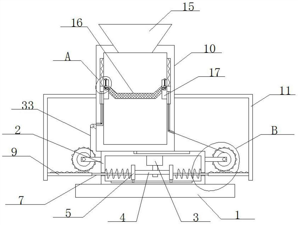
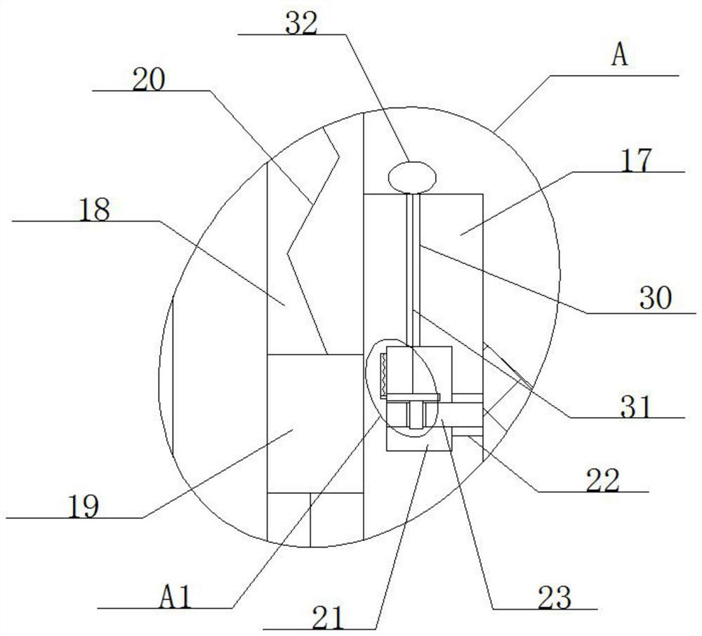
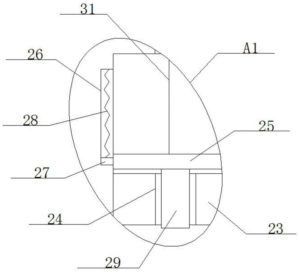
[0027] Refer Figure 1-5 A plastic production powder apparatus, including the base 1, the top of the base 1 fixedly mounted, and the inner wall of the top of the casing 2 is fixedly mounted, and the motor 3 is fixed to the output shaft of the motor 3 fixing a cam. 4, sliding on the inner wall of the bottom of the casing 2, two mobile rods 5 are slidably mounted, and the two mobile rods 5 are in contact with the long-diameter end and the short-diameter end of the cam 4, and the inner walls of the casing 2 are opened. Have a cross hole 6, and the two mobile rods 5 are fixedly mounted on one end of the crossbar 7, and the other end of the crossbar 7 penetrates the cross hole 6, and extends to the casing 2, two crossbar 7 At one end distance from each other, the rack 9 is fixedly mounted, and the top side slide is slidably mounted with the separation tank 10 in the top side of the casing 2, and the two racks 9 are fixed to each other, and the L-type rod 11 is fixedly
Example Embodiment
[0035] Example 2
[0036]Refer Figure 1-5 A plastic production powder apparatus, including the base 1, the top of the base 1 fixedly mounted, and the inner wall of the top of the casing 2 is fixedly mounted, and the motor 3 is fixed to the output shaft of the motor 3 fixing a cam. 4, sliding on the inner wall of the bottom of the casing 2, two mobile rods 5 are slidably mounted, and the two mobile rods 5 are in contact with the long-diameter end and the short-diameter end of the cam 4, and the inner walls of the casing 2 are opened. Have a cross hole 6, and the two mobile rods 5 are fixedly mounted on one end of the crossbar 7, and the other end of the crossbar 7 penetrates the cross hole 6, and extends to the casing 2, two crossbar 7 At one end distance from each other, the rack 9 is fixedly mounted, and the top side slide is slidably mounted with the separation tank 10 in the top side of the casing 2, and the two racks 9 are fixed to each other, and the L-type rod 11 is fixedly mou
Example Embodiment
[0044] Example three
[0045] Refer Figure 1-5 A plastic production powder apparatus, including the base 1, the top of the base 1 fixedly mounted, and the inner wall of the top of the casing 2 is fixedly mounted, and the motor 3 is fixed to the output shaft of the motor 3 fixing a cam. 4, sliding on the inner wall of the bottom of the casing 2, two mobile rods 5 are slidably mounted, and the two mobile rods 5 are in contact with the long-diameter end and the short-diameter end of the cam 4, and the inner walls of the casing 2 are opened. Have a cross hole 6, and the two mobile rods 5 are fixedly mounted on one end of the crossbar 7, and the other end of the crossbar 7 penetrates the cross hole 6, and extends to the casing 2, two crossbar 7 At one end distance from each other, the rack 9 is fixedly mounted, and the top side slide is slidably mounted with the separation tank 10 in the top side of the casing 2, and the two racks 9 are fixed to each other, and the L-type rod 11 is fixedl
PUM
 Abstract
Description
Claims
Application Information
 - R&D Engineer
- R&D Manager
- IP Professional
- Industry Leading Data Capabilities
- Powerful AI technology
- Patent DNA Extraction
Browse by: Latest US Patents, China's latest patents, Technical Efficacy Thesaurus, Application Domain, Technology Topic.
© 2024 PatSnap. All rights reserved.Legal|Privacy policy|Modern Slavery Act Transparency Statement|Sitemap