Oil stain isolation device facilitating oil stain collection and used for flat wire production

An isolation device and oil pollution technology, which is applied in the direction of processing textile material equipment configuration, removing liquid/gas/vapor by scraping, processing textile material carrier, etc. The effect of reducing pollution

Pending Publication Date: 2021-06-11
句容建荣汽配有限公司
View PDF10 Cites 0 Cited by
  • Summary
  • Abstract
  • Description
  • Claims
  • Application Information

AI Technical Summary

Benefits of technology

This patented technology allows for better control over how thin metal wires enter devices compared with traditional methods like rolling them onto paper or placing it under tension during manufacturing processes. It also includes various technical features including lubrication systems, heat dissipating arrangements, and clean-up mechanisms. Overall, this innovative process helps improve efficiency while reducing environmental concerns associated therewith.

Problems solved by technology

This patented technical problem addressed by this patents relates to improving the efficiency and effectiveness of producing high quality flatteny wires used in industrial applications such as automobile seat backs or car headrests. Current methods involve multiple steps involving different treatment agents like acidic degreasing agent (A), water washing/dewatering agent) followed by dry cleaning before further processing. These processes can result in excessive use of energy resources due to the large amount of oily residue left behind after each step. Additionally, these conventional techniques often require long periods of exposure times while collecting samples from the surface being treated.

Method used


Image

  • Oil stain isolation device facilitating oil stain collection and used for flat wire production
  • Oil stain isolation device facilitating oil stain collection and used for flat wire production
  • Oil stain isolation device facilitating oil stain collection and used for flat wire production

Examples


Embodiment Construction

[0020] The technical solutions in the embodiments of the present invention will be clearly and completely described below with reference to the accompanying drawings in the embodiments of the present invention. Obviously, the described embodiments are only a part of the embodiments of the present invention, but not all of the embodiments. Based on the embodiments of the present invention, all other embodiments obtained by those of ordinary skill in the art without creative efforts shall fall within the protection scope of the present invention.

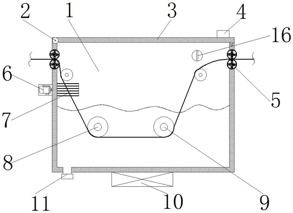
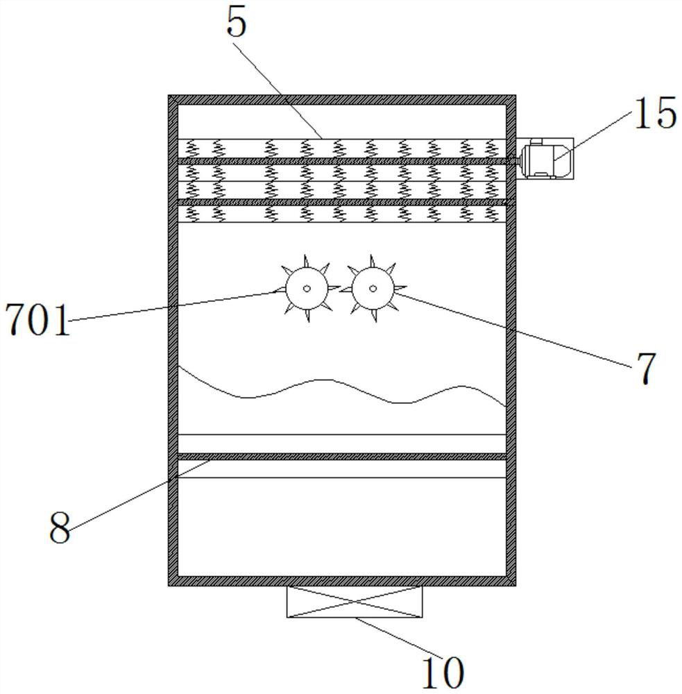
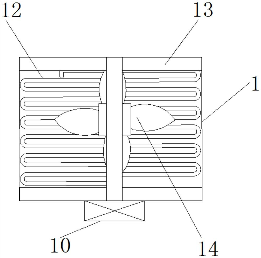
[0021] see Figure 1-5 , The present invention provides a technical solution: an oil pollution isolation device for flat wire production that is convenient for oil pollution collection, comprising a device main body 1, a first rotating shaft 2, a device upper cover 3, an upper cover handle 4, a first roller 5, a roller Outer casing 501, spring 502, second rotating shaft 503, first motor 6, oil scraper 7, scraper 701, second roller 8, thi


PUM


Abstract

The invention discloses an oil stain isolation device facilitating oil stain collection and used for flat wire production. The oil stain isolation device comprises a device main body and a first rotating shaft; the first rotating shaft is fixed above the inner wall of the left side of the device main body; the surface of the first rotating shaft is connected with a device upper cover; an upper cover handle is fixed to the upper portion of the device upper cover; first rollers are fixed to the upper portions of the two side walls of the device main body; second motors are fixed to the outer sides of the first rollers; springs are fixed to the inner sides of the first rollers; second rotating shafts are fixed to the tails of the springs; a fan is fixed to the surface of a fixed frame; a duckbilled spray head is arranged on the inner wall of the right side in the device main body; and an oil pump is arranged in the device. Used oil can be pumped into a copper pipe and cooled by the external fan, and then the duckbilled spray head sprays the oil into the device, so that the oil can be repeatedly used, and the pollution caused by oil dirt to the environment is reduced while the cost is reduced; and the device is more practical.

Description


Claims


Application Information

Patent Timeline
Owner 句容建荣汽配有限公司
Why Eureka
Try Eureka