Fatigue testing device for swing rotating shaft

A technology of fatigue testing and rotating shafts, which is applied in the direction of measuring devices, testing of mechanical components, testing of machine/structural components, etc., can solve the problems of difficult to control the amplitude of swing, low efficiency, time consumption, etc., and achieve accurate feedback adjustment Effect

Inactive Publication Date: 2021-06-22
TUV RHEINLAND SHANGHAI
View PDF9 Cites 0 Cited by
  • Summary
  • Abstract
  • Description
  • Claims
  • Application Information

AI Technical Summary

Problems solved by technology

The mechanical strength of the shaft outer tube 141, the inner shaft 142, and the connecting plate 145 in the above structure and the stability of their cooperation are the key to determinin

Method used


Image

  • Fatigue testing device for swing rotating shaft
  • Fatigue testing device for swing rotating shaft

Examples


Embodiment

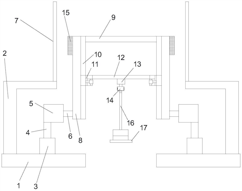
[0038] The fatigue test device used for the swing shaft in the present invention includes a base 1, a frame body 2, an angle plate 7, a height adjustment unit 3, a swing motor 5, an eccentric rod 8, a guide rod 10, a sliding unit 11, and a second connecting rod 12 , shaft connection unit 13 and load assembly, see figure 1 .

[0039] There are two bases 1 arranged symmetrically, so all components in the technical solution are arranged symmetrically. The frame body 2 is arranged on the base 1 , and the frame body is mainly provided for placing the angle plate 7 . The angle plate 7 is vertically arranged on the frame body 2, and an angle scale of 0-180 degrees is marked on the angle plate.

[0040] The height adjustment unit 3 is arranged on the base 1, and the height adjustment push shaft 4 of the height adjustment unit 3 is vertically upward; the swing motor 5 is arranged on the height adjustment push shaft 4, and the swing output shaft 6 of the swing motor 5 is Horizontal ori


PUM


Abstract

The invention relates to a fatigue testing device for a swing rotating shaft, which comprises two bases, a frame body, an angle scale, two height adjusting units, two swing motors, two eccentric rods, a guide rod, a sliding unit, a second connecting rod, a rotating shaft connecting unit and a load assembly, wherein the swing motor is arranged on a height adjusting push shaft, one end of the eccentric rod is connected with a swing output shaft, and the other end of the eccentric rod is connected with a first connecting rod. The guide rod is arranged on the eccentric rod, the sliding unit is arranged on the guide rod, and adjustment of the distance between the axis of the second connecting rod and the axis of the swing output shaft is achieved through position adjustment of the sliding unit. The rotating shaft connecting unit is arranged in the middle of the second connecting rod. A swing rotating shaft to be tested is connected below the rotating shaft connecting unit. Compared with the prior art, the swing load is multiplied through a structure capable of flexibly adjusting the eccentric distance, and the eccentric distance is adjusted through the cooperation of the sliding unit and the guide rod, so that different test strengths are matched according to different test standards.

Description


Claims


Application Information

Patent Timeline
Owner TUV RHEINLAND SHANGHAI
Why Eureka
Try Eureka