Hydraulic pulsation assisted nitrogen-chemical flooding ground control device and implementation method
A surface control device and chemical flooding technology, which is applied in the direction of earthwork drilling, wellbore/well components, production fluid, etc., can solve the problems of insufficient contact and mixing of heavy oil and gas or chemical agents, and reduce laying , easy operation and cost-saving effect
- Summary
- Abstract
- Description
- Claims
- Application Information
AI Technical Summary
Benefits of technology
Problems solved by technology
Method used
Image

Examples
Embodiment 1
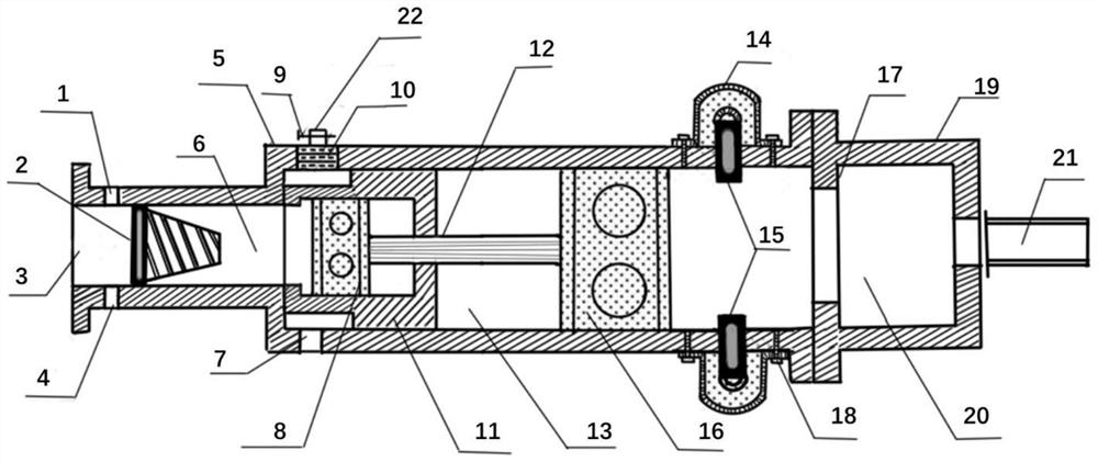
[0039] A hydraulic pulsation assisted nitrogen-chemical flooding ground control device, including a pulsation generator 5 .
[0040] The pulsation generator is a hollow lumen, one end of the lumen is an inlet, the wall of the lumen is provided with an outlet, the other end of the lumen is open and connected to a hydraulic cylinder block 19 , and the hydraulic cylinder block is connected to a pressure transmission tube 21 .
[0041]Gas injection inlet 1, liquid injection inlet 3 and chemical agent injection inlet 4 are respectively set at the inlet, and a hydrocyclone 2 is arranged inside the inlet, and the hydrocyclone plays a mixing role after the three injection channels at the inlet, single-phase When the liquid is injected, it only plays an energy-increasing role. The outlet includes a normal outlet 7 and an atomization outlet 22. A sleeve 11 is arranged inside the lumen of the pulsation generator, and a main piston 8 is arranged inside the sleeve. One end of the sleeve is op
Embodiment 2
[0045] A hydraulic pulsation assisted nitrogen-chemical flooding ground control device, its structure is as described in Embodiment 1, the difference is that the lumen behind the hydrocyclone 2 is a gas-liquid mixing chamber 6, and the length of the gas-liquid mixing chamber is greater than Hydrocyclone length. The gas and liquid are fully mixed in the mixing chamber.
Embodiment 3
[0047] A hydraulic pulsation assisted nitrogen-chemical flooding ground control device, its structure is as described in Embodiment 1, the difference is that the atomization outlet 22 includes an atomizer 10 and a one-way valve 9; the normal outlet is provided with a one-way valve valve. The outlet is located on the lumen wall at one end of the gas-liquid mixing chamber. Both the main piston and the piston are fixed on the piston rod. When the piston drives the sleeve away from the gas-liquid mixing chamber to the stroke limiter, the fluid can reach the outlet.
PUM
| Property | Measurement | Unit |
|---|---|---|
| Density | aaaaa | aaaaa |
| Viscosity | aaaaa | aaaaa |
| Viscosity | aaaaa | aaaaa |
Abstract
Description
Claims
Application Information
 - R&D Engineer
- R&D Manager
- IP Professional
- Industry Leading Data Capabilities
- Powerful AI technology
- Patent DNA Extraction
Browse by: Latest US Patents, China's latest patents, Technical Efficacy Thesaurus, Application Domain, Technology Topic.
© 2024 PatSnap. All rights reserved.Legal|Privacy policy|Modern Slavery Act Transparency Statement|Sitemap