Network technology peep-proof automatic power-off lifting camera

A technology of automatic power-off and network technology, applied in the field of network technology, can solve the problems of increasing the risk of camera damage, the camera does not have the function of automatic power-off and anti-peeping, and the camera cannot be automatically raised and lowered, so as to reduce the risk of damage and protect personal privacy , Good effect on personal privacy

Inactive Publication Date: 2021-06-25
广州星亮科技有限公司
View PDF0 Cites 2 Cited by
  • Summary
  • Abstract
  • Description
  • Claims
  • Application Information

AI Technical Summary

Benefits of technology

This patented innovative technology helps protect cameras from being damaged during transport or storage without having them taken out for maintenance purposes due to their weight. It also makes it easier to store these cameras with other things inside while still providing effective self-lifting functions. Additionally, there are features like autoimmune lamps on top of the camera's coverings which help reduce potential harm caused by lightning strikes. Overall, this new design improves safety measures against damage to the equipment used within surveillance systems.

Problems solved by technology

The technical problem addressed by this patented solution relates to protecting sensitive equipment from being exposed during data transmission or storage without having them turn over their functions when they shouldn't for communication purposes (such as recording). This can lead to damaging effects such as scratches caused by external factors like rainwater hitting the camera lens surface causing it to lose its effectiveness due to water pressure.

Method used


Image

  • Network technology peep-proof automatic power-off lifting camera
  • Network technology peep-proof automatic power-off lifting camera
  • Network technology peep-proof automatic power-off lifting camera

Examples


Embodiment Construction

[0025] The following will clearly and completely describe the technical solutions in the embodiments of the present invention with reference to the accompanying drawings in the embodiments of the present invention. Obviously, the described embodiments are only some, not all, embodiments of the present invention. Based on the embodiments of the present invention, all other embodiments obtained by persons of ordinary skill in the art without making creative efforts belong to the protection scope of the present invention.

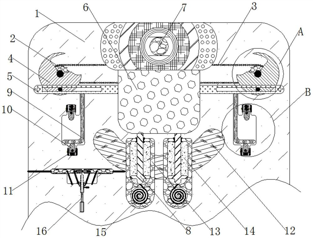
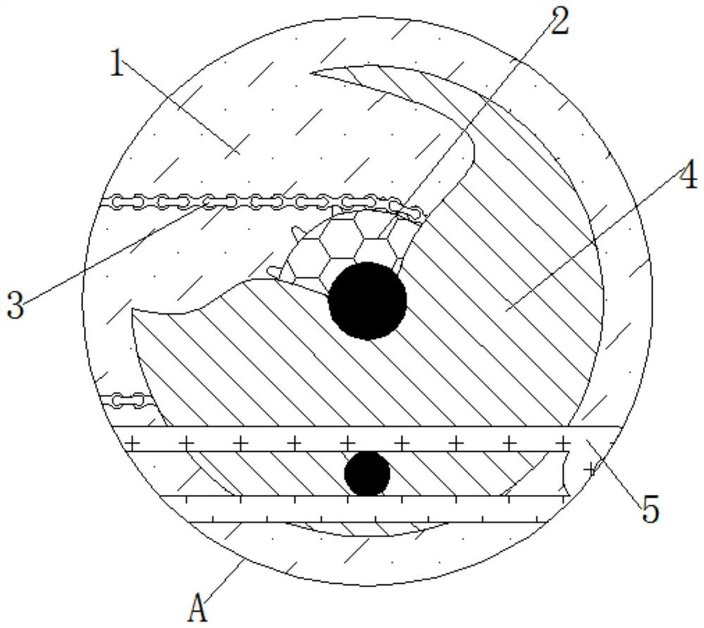
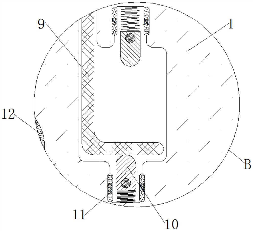
[0026] see Figure 1-4 , a network technology anti-peeping automatic power-off lifting camera, including a casing 1, the inside of the casing 1 is rotatably connected to a driving wheel 2, the outside of the driving wheel 2 is meshed with a chain 3, and the outside of the driving wheel 2 is fixedly connected to a rotating ring 4 , the external movement of the rotating circle 4 is connected with a linkage rod 5, the outside of the linkage rod 5 is fixedly connecte


PUM


Abstract

The invention relates to the technical field of network technology, and discloses a network technology peep-proof automatic power-off lifting camera. The camera comprises a shell; a driving wheel is rotationally connected to the interior of the shel; a chain is meshed with the exterior of the driving wheel; a rotating ring is fixedly connected to the exterior of the driving wheel, and a linkage rod is movably connected to the exterior of the rotating ring. A lifting table is fixedly connected to the exterior of the linkage rod, a camera is fixedly connected to the top of the lifting table, a movable rod is fixedly connected to the bottom of the lifting table, a bent rod is slidably connected to the interior of the shell, and a trigger block is slidably connected to the interior of the shell; Through mutual cooperative use of the shell, the driving wheel, the chain, the rotating ring, the linkage rod, the lifting table, the camera, a movable rod, a bent rod, a trigger block, a magnetic plate assembly, an electromagnet I, a sealing shell, magnetorheological fluid and a torsional spring, when the camera is used, the effect of an automatic lifting function can be achieved through automatic operation of the mechanisms.

Description


Claims


Application Information

Patent Timeline
Owner 广州星亮科技有限公司
Why Eureka
Try Eureka