Water supply equipment with underwater acoustic communication and water supply system

A technology of water supply equipment and underwater acoustic communication, which is applied in the direction of water supply pipeline system, signal transmission system, non-electrical signal transmission system, etc. It can solve the problems of increased electric shock risk, high construction and maintenance costs, unstable communication, etc. stable effect

Pending Publication Date: 2021-07-16
QINGDAO HAIER SMART TECH R & D CO LTD +1
View PDF0 Cites 0 Cited by
  • Summary
  • Abstract
  • Description
  • Claims
  • Application Information

AI Technical Summary

Benefits of technology

This patented technology allows for better monitoring or controlling overwater assets like pipes without affecting their physical properties (like wall thickness). It uses sound signals that are sent through the pipeline instead of just being reflected back into space where they were captured. By sending these sounds along the way it helps avoid interference between them when trying to communicate across long distance paths. Overall, this system provides faster response times than current methods while also reducing errors caused due to subjective variables like material used around the asset.

Problems solved by technology

This patented describes how current wireless or wireline connections used with traditional gas water supply systems have limitations when applied indoors due to their location at varying distances from each other. These issues lead to difficulties during network management and troubleshooting operations that require long hours and expensive equipment.

Method used


Image

  • Water supply equipment with underwater acoustic communication and water supply system
  • Water supply equipment with underwater acoustic communication and water supply system
  • Water supply equipment with underwater acoustic communication and water supply system

Examples


Embodiment Construction

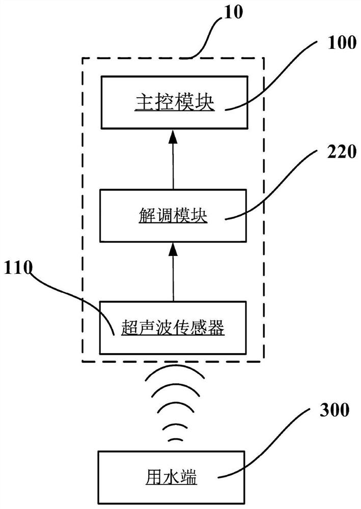
[0034] figure 1 It is a working principle block diagram of the water supply equipment according to one embodiment of the present invention. The water supply device 10 with underwater acoustic communication may generally include an ultrasonic sensor 110 , a demodulation module 220 and a main control module 100 which are electrically connected in sequence.

[0035] The ultrasonic sensor 110 is arranged in the water pipe connected with the water supply equipment 10 . The ultrasonic sensor 110 is a sensor that converts ultrasonic signals into other energy signals. In the embodiment of the present application, the ultrasonic sensor 110 is configured to receive the ultrasonic signal propagating at the first modulation frequency in the water pipe and convert the ultrasonic signal into a received electrical signal. Signal.

[0036] The demodulation module 220 is configured to demodulate the control instruction from the received electrical signal. The ultrasonic signal in the water pipe


PUM


Abstract

The invention provides water supply equipment with underwater acoustic communication, and the equipment comprises an ultrasonic sensor, a demodulation module and a main control module; the ultrasonic sensor is arranged in a water pipe connected with the water supply equipment and is configured to receive an ultrasonic signal transmitted in the water pipe and convert the ultrasonic signal into a receiving electric signal; the demodulation module is configured to demodulate a control instruction from the received electric signal, and the main control module is configured to control the water supply equipment to execute the control instruction. The invention further provides a water supply system comprising the water supply equipment. Communication between the water supply equipment and the water using ends is achieved through ultrasonic waves, communication between the water supply equipment and the multiple water using ends far away from one another can be not affected by factors such as walls, transmission is rapid and stable, and application and popularization are easy.

Description


Claims


Application Information

Patent Timeline
Owner QINGDAO HAIER SMART TECH R & D CO LTD
Why Eureka
Try Eureka