Manufacturing process of optical cable

A manufacturing process and technology for optical cables, applied in optics, light guides, optical components, etc., can solve problems such as inconvenient construction, ointment outflow, and difficulty in cleaning ointment, and achieve the effect of convenient construction

Active Publication Date: 2021-07-23
FUTONG GRP JIASHAN COMM TECH CO LTD
View PDF10 Cites 0 Cited by
  • Summary
  • Abstract
  • Description
  • Claims
  • Application Information

AI Technical Summary

Problems solved by technology

This structure will cause more ointment to flow out during construction, and the ointment is difficult

Method used


Image

  • Manufacturing process of optical cable
  • Manufacturing process of optical cable
  • Manufacturing process of optical cable

Examples


Embodiment Construction

[0061] Below in conjunction with each accompanying drawing, the present invention is described in detail.

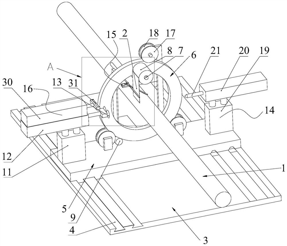
[0062] Such asfigure 1 Shown, a kind of manufacturing process of optical cable, comprises the following steps:

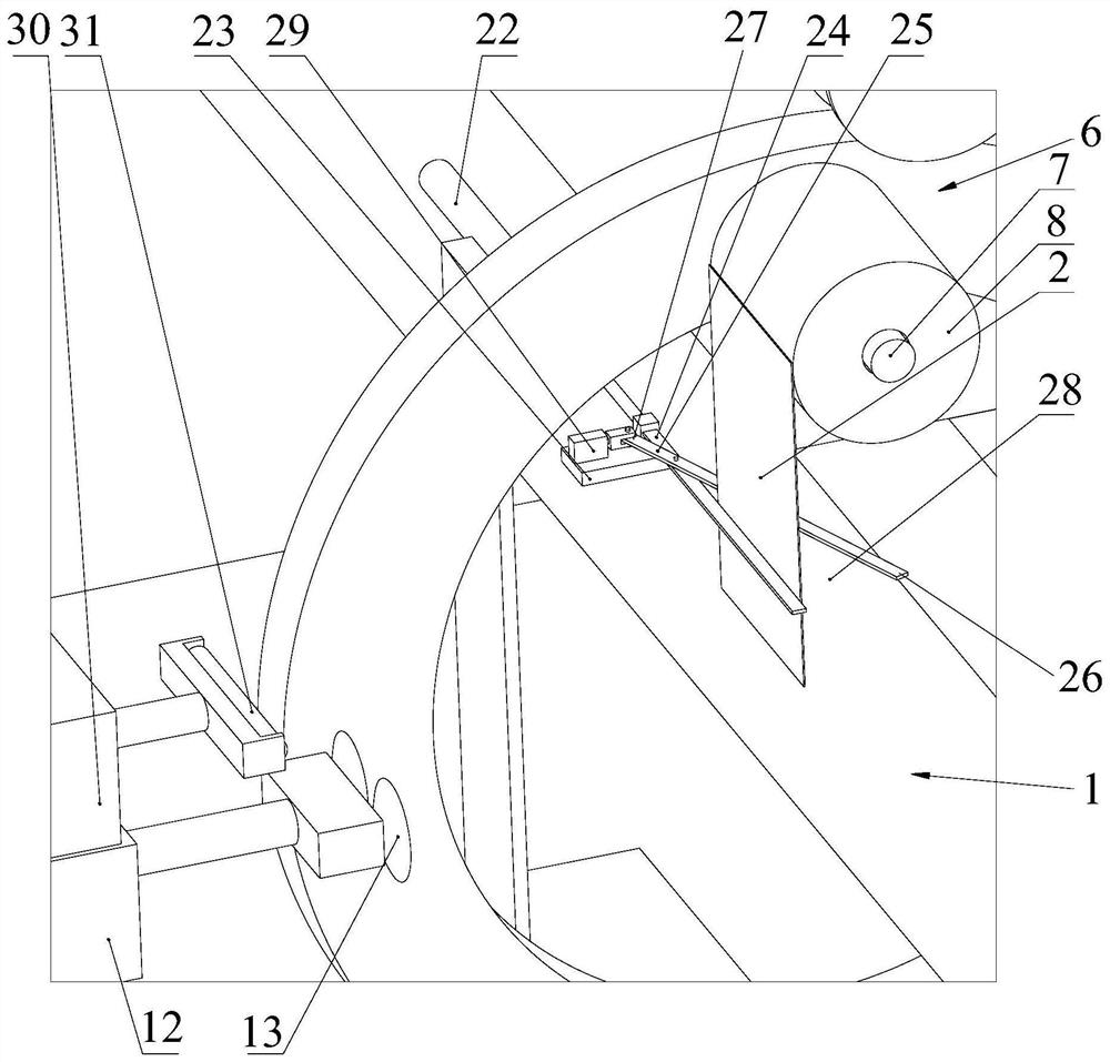
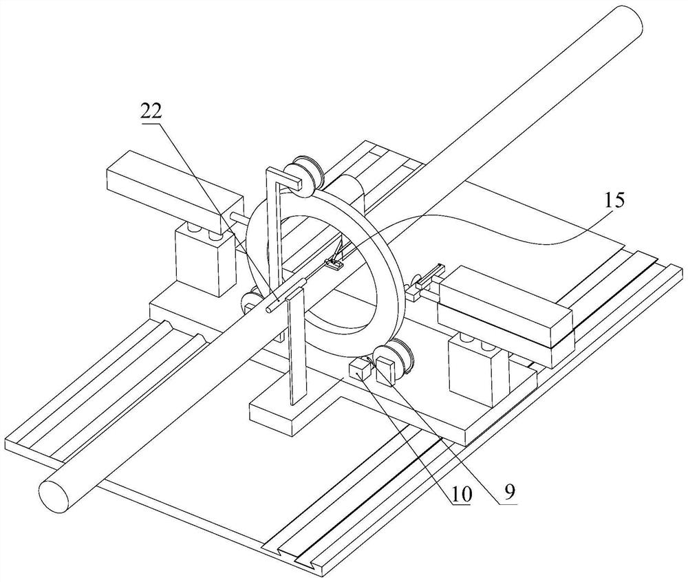
[0063] 1) A water blocking tape 2 is wound around the outer side of the cable core 1 at intervals;

[0064] 2) The cable core 1 enters the ointment device to apply ointment;

[0065] 3) The cable core 1 enters the extrusion device, and the outer sheath is processed on the outside of the cable core 1;

[0066] 4) Cool and dry the outer sheath, and then spray identification marks on the corresponding positions of the outer sheath and the dry waterproof jacket.

[0067] In the present application, the water-blocking strips 2 are arranged at intervals before the cable core 1 is coated with ointment, so that there is basically no ointment in the section where the water-blocking strips 2 are located after the cable core 1 has gone through the ointment process. Durin


PUM


Abstract

The invention discloses a manufacturing process of an optical cable. The manufacturing process comprises the following steps: 1) winding a water-blocking tape on the outer side of a cable core at intervals; (2) enabling the cable core to enter a paste coating device to be coated with ointment; (3) enabling the cable core to enter an extrusion molding device, and processing an outer sheath on the outer side of the cable core; and 4) cooling and drying the outer sheath, and then spraying an identification mark at the corresponding position of the outer sheath and the dry-type waterproof jacket. According to the application, the water-blocking tapes are arranged at intervals before the cable core is coated with the ointment, so that after the cable core is coated with the ointment, the sections where the water-blocking tapes are located basically have no ointment. During actual construction, the optical cable is cut off at the identification mark, at the moment, no ointment flows out of the section of the optical cable between the cable core and the outer sheath, and the optical cable is more convenient to construct.

Description


Claims


Application Information

Patent Timeline
Owner FUTONG GRP JIASHAN COMM TECH CO LTD
Why Eureka
Try Eureka