Flange heater

A heater and flange technology, applied in the field of heaters, can solve the problems of insufficient uniform heating, unsatisfactory heating, single heating method, etc., and achieve the effect of good heating effect and uniform heating

Pending Publication Date: 2021-07-27
ANHUI HUARUI ELECTRIC
View PDF5 Cites 0 Cited by
  • Summary
  • Abstract
  • Description
  • Claims
  • Application Information

AI Technical Summary

Benefits of technology

This patented design allows for efficient cooling by circulating outside air into the device while controllably adjusting temperature within the device's housing. By connecting this external air with the inner part of the machine being controlled (the electrothermal wire) via pipes, energy efficiency becomes higher compared to traditional systems without any extra equipment like fans.

Problems solved by technology

This patented technical solution describes different types of electric heators: flanged type heaters (FH), linear induction motive force generators (LIM) and inductor systems. These devices have their own advantages but also drawbacks like being limited by environmental factors during operation. Flexible thermal insulation materials made from silicone rubber allow for better moisture management while maintaining efficient heat transfer through air flow. Additionally, these solutions require specific components inside the device itself, leading to potential issues related to manufacturing variations overtime.

Method used


Image

  • Flange heater
  • Flange heater
  • Flange heater

Examples


Embodiment 1

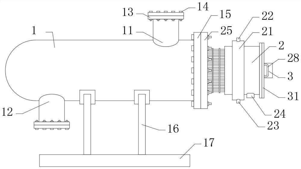
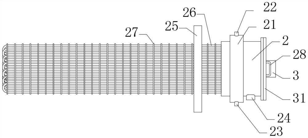
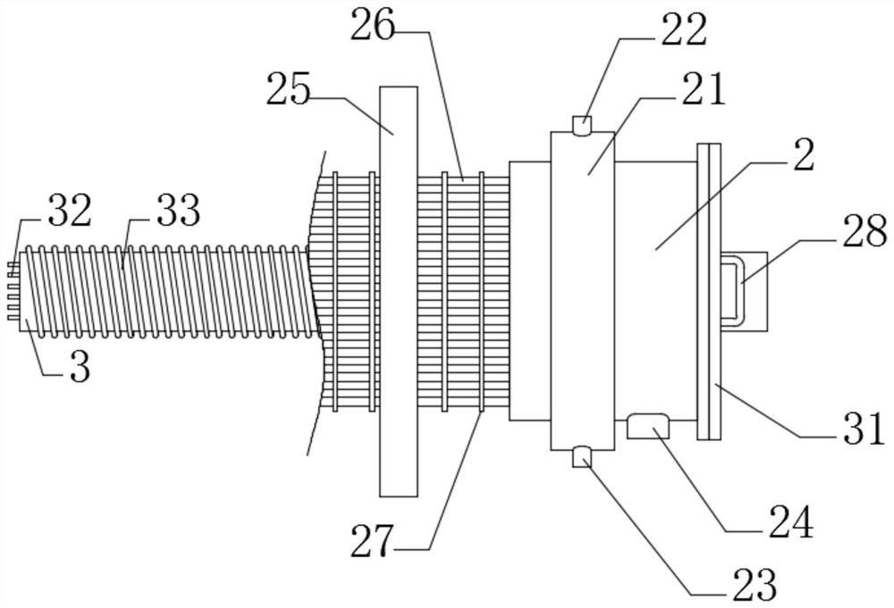
[0025] Please refer to figure 1 , figure 2 , image 3 and Figure 4 ,in, figure 1 It is a schematic structural diagram of the overall front view of the present invention; figure 2 It is a schematic diagram of the main viewing mechanism of the control box of the present invention; image 3 It is a schematic diagram of the front half-section structure of the control box of the present invention; Figure 4 It is a schematic diagram of the side view structure of the outer air intake pipe of the present invention; specifically, a flange heater includes: a main body 1, an air inlet 11 is inlaid on the upper side of the main body 1, and a lower part of the main body 1 The side is inlaid with an exhaust port 12, and the air inlet 11 and the exhaust port 12 are welded with an air inlet flange 13, and bolts 14 are installed on the air inlet flange 13, and the main body 1 One end is welded with sealing flange 15.

[0026] In the control box 2, a fixed flange 25 is installed on one

Embodiment 2

[0031] Please refer to figure 1 , figure 2 , image 3 and Figure 4 ,in, figure 1 It is a schematic structural diagram of the overall front view of the present invention; figure 2 It is a schematic diagram of the main viewing mechanism of the control box of the present invention; image 3 It is a schematic diagram of the front half-section structure of the control box of the present invention; Figure 4 It is a schematic diagram of the side view structure of the outer air intake pipe of the present invention; specifically, a flange heater includes: a main body 1, an air inlet 11 is inlaid on the upper side of the main body 1, and a lower part of the main body 1 The side is inlaid with an exhaust port 12, and the air inlet 11 and the exhaust port 12 are welded with an air inlet flange 13, and bolts 14 are installed on the air inlet flange 13, and the main body 1 One end is welded with sealing flange 15.

[0032] In the control box 2, a fixed flange 25 is installed on one


PUM


Abstract

One or more embodiments of the invention provide a flange heater. The flange heater comprises a body and a control box. An air inlet is embedded in one side of the upper portion of the body, an exhaust opening is embedded in one side of the lower portion of the body, and bolts are mounted on an air inlet flange. A fixing flange is installed on one side of a sealing flange through bolt, electric heating tubes are evenly embedded in the fixing flange, a fixing disc is welded to the peripheries of the electric heating tubes, and a wire hole is embedded in the position, close to one side, of the bottom end of the control box. The air inlet is used for introducing air inside, the control box is used for controlling and heating the internal electric heating tubes, so that the introduced air is heated, an electromagnetic heating coil is used for heating internal heat storage rods and the like, the surrounding air is indirectly heated to achieve the heating effect, and therefore when the flange heater is used, air is heated in two different heating manners of the flange heater, so that the heating effect of the flange heater is better, and heating is more uniform.

Description


Claims


Application Information

Patent Timeline
Owner ANHUI HUARUI ELECTRIC
Why Eureka
Try Eureka