Gas engine power plant and method of operating a gas engine power plant

A gas engine and power device technology, applied in the direction of engine components, combustion engines, engine control, etc., can solve the problem that energy cannot be used effectively

Active Publication Date: 2021-08-06
WARTSILA FINLAND OY
View PDF8 Cites 0 Cited by
  • Summary
  • Abstract
  • Description
  • Claims
  • Application Information

AI Technical Summary

Problems solved by technology

[0002] It is well known in the field of internal combustion piston engines that a considerable portion

Method used


Image

  • Gas engine power plant and method of operating a gas engine power plant

Examples


Embodiment Construction

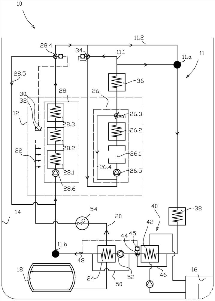
[0025] figure 1 A gas engine power plant 10 is schematically depicted comprising at least one dual fuel internal combustion engine 12 , hereinafter referred to as the engine. A dual fuel engine is a piston engine that can run on both gaseous and liquid fuels. When running in gas mode, the engine works according to the Otto process, in which a lean air-fuel mixture is used for combustion. When running in diesel mode, the engine works according to the Diesel process. The engine is optimized to run on gaseous fuel, and diesel fuel is used for backup fuel operation. During operation, switching between fuels occurs seamlessly without loss of power or speed. exist figure 1 Among them, the power plant 10 is in a sea vessel 14 for generating propulsion and / or electric power for the sea vessel 14 . The sea vessel is provided with sea suction tanks 16 which provide sea water in the sea vessel 14 for cooling purposes. Power-plant 10 includes cryogenic fuel storage, or cryogenic tank


PUM


Abstract

Invention relates to a gas engine power plant (10) comprising at least one dual fuel internal combustion engine (12) configured to run by burning gas fuel, a cryogenic fuel storage (18) for storing gas fuel in liquefied form for use of the engine (12), a fuel feed line (20) between the cryogenic fuel storage (18) and the at least one dual fuel internal combustion engine (12), a main gas evaporator (24) arranged to the fuel feed line (20) and configured to evaporate the liquefied gas for use by the at least one dual fuel internal combustion engine (12), a heat transfer circuit (11) configured to circulate heat transfer fluid in the circuit for transferring heat from the at least one dual fuel engine (12) to heat transfer fluid, a central heat transfer fluid cooler system (40) arranged to the heat transfer circuit (11) and where the main gas evaporator (24) is arranged into heat transfer communication with the heat transfer circuit (11) after the central fluid cooler system (40) in the flow direction of the heat transfer fluid such that heat transfer fluid temperature entering the main gas evaporator (24) is controllable by the central cooler system (40). Invention relates also to a method of operating a gas engine power plant (10).

Description


Claims


Application Information

Patent Timeline
Owner WARTSILA FINLAND OY
Why Eureka
Try Eureka