Metal packaging tin forming machining machine and machining method

A technology of forming processing and packaging cans, which is applied in the field of packaging cans processing, can solve the problems of punching position changes, work process interference, and waste of working time, so as to avoid replacement and improve processing efficiency.

Inactive Publication Date: 2021-08-10
义乌市伟硕包装科技有限公司
View PDF0 Cites 2 Cited by
  • Summary
  • Abstract
  • Description
  • Claims
  • Application Information

AI Technical Summary

Problems solved by technology

[0005] The invention can solve the problem that the traditional metal packaging cans can only be cut out of fixed-length metal plates when forming and processing. When it is necessary to make metal cans with different diameters, it is necessary to replace the equipment for processing, which wastes working time and causes The processing efficiency of the overall

Method used


Image

  • Metal packaging tin forming machining machine and machining method
  • Metal packaging tin forming machining machine and machining method
  • Metal packaging tin forming machining machine and machining method

Examples


Embodiment Construction

[0034] The embodiments of the present invention will be described in detail below with reference to the accompanying drawings, but the present invention can be implemented in many different ways defined and covered by the claims.

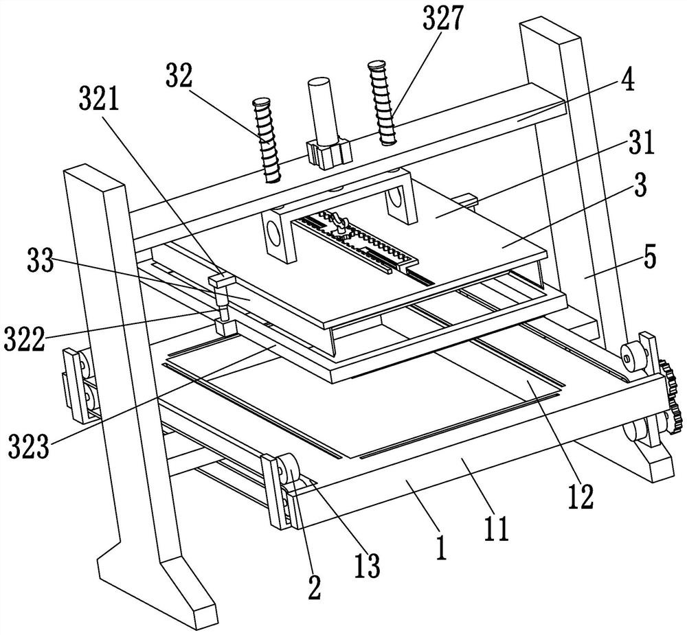
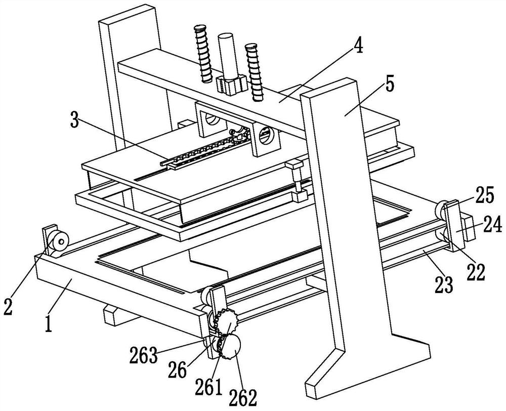
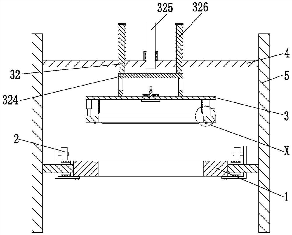
[0035] like Figure 1 to Figure 6 As shown, a metal packaging can molding processing machine includes a working base 1, an intermittent driving device 2, a punching device 3, a mounting plate 4, and a mounting base 5. The working base 1 is provided with an intermittent driving device 2, A punching device 3 is arranged above the intermittent driving device 2, and the punching device 3 is installed on a mounting plate 4, and the left and right ends of the mounting plate 4 are symmetrically connected with mounting bases 5.

[0036] The working base 1 comprises a working plate 11, a square discharge port 12 and a working groove 13, the middle part of the working plate 11 is provided with a square discharging port 12, and the left and right ends of the workin


PUM


Abstract

The invention relates to a metal packaging tin forming machining machine and machining method. The metal packaging tin forming machining machine comprises a working bottom plate, an intermittent driving device, a blanking device, a mounting plate and mounting bases, the working bottom plate is provided with the intermittent driving device, the blanking device is arranged above the intermittent driving device, and the blanking device is mounted on the mounting plate. The mounting bases are symmetrically connected to the left and right ends of the mounting plate. The following problems can be solved that when a traditional metal packaging tin is subjected to forming machining, only a metal plate with the fixed length can be cut, when metal tins with different diameters need to be manufactured, equipment needs to be replaced for machining, the working time is wasted, the machining efficiency of the whole device is reduced, and after blanking is completed, and when a blanking knife moves upwards, the metal coiled material is easily brought out, the tensioning degree of the metal coiled material is damaged, the whole working process is possibly interfered, and the blanking position is changed.

Description


Claims


Application Information

Patent Timeline
Owner 义乌市伟硕包装科技有限公司
Why Eureka
Try Eureka