LED control system

A control system and LED light string technology, applied in the direction of electrical components, etc., can solve the problems of complex structure and high cost of LED control system, and achieve the effect of low cost, high reliability and simple implementation

Pending Publication Date: 2021-08-10
WUXI DECHIP MICROELECTRONICS CO LTD
View PDF0 Cites 2 Cited by
  • Summary
  • Abstract
  • Description
  • Claims
  • Application Information

AI Technical Summary

Benefits of technology

This patented technology allows for easy communication between different devices without requiring complicated sorting processes like this one used with analog signaling methods such as radio waves or infrared (IR) sensors. It also simplifies the process while maintains its effectiveness over time due to it being able to communicate both types of data simultaneously through standardized protocols that are easier to implement than traditional means.

Problems solved by technology

The technical problem addressed by this patented technology relates to improving the efficiency and effectiveness of LED displays that require precise voltage levels and control over their brightness without requiring expensive signal transmission systems like cables between them.

Method used


Image

  • LED control system
  • LED control system
  • LED control system

Examples


Embodiment Construction

[0044] It should be noted that, in the case of no conflict, the embodiments of the present invention and the features in the embodiments can be combined with each other. The present invention will be described in detail below with reference to the accompanying drawings and examples.

[0045] In order to enable those skilled in the art to better understand the solutions of the present invention, the following will clearly and completely describe the technical solutions in the embodiments of the present invention in conjunction with the accompanying drawings in the embodiments of the present invention. Obviously, the described embodiments are only Embodiments of some, but not all, embodiments of the present invention. Based on the embodiments of the present invention, all other embodiments obtained by persons of ordinary skill in the art without making creative efforts shall fall within the protection scope of the present invention.

[0046] It should be noted that the terms "firs


PUM


Abstract

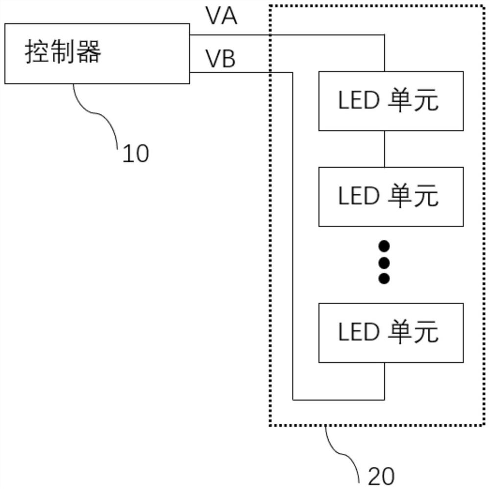
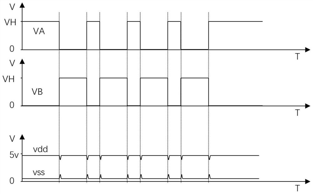
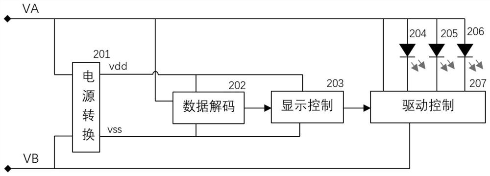
The invention relates to the technical field of LED control, and particularly discloses an LED control system which comprises a controller and an LED lamp string electrically connected with the controller, wherein the controller comprises a first data output port and a second data output port and is used for sending out a first data signal through the first data output port and sending out a second data signal through the second data output port, and the first data signal and the second data signal are opposite in phase; and the LED lamp string can receive the first data signal and the second data signal through a data receiving port, can realize display control of the LED lamp according to the first data signal and the second data signal, and can perform power supply conversion on the first data signal and the second data signal to realize power supply of the LED lamp. The LED control system provided by the invention is simple in implementation mode, low in cost and high in reliability.

Description


Claims


Application Information

Patent Timeline
Owner WUXI DECHIP MICROELECTRONICS CO LTD
Why Eureka
Try Eureka