Medical wound cleaning device control circuit
A cleaning device and control circuit technology, applied in the medical field, can solve problems such as inconvenient work for medical staff, wound cleaning and disinfection tools without lighting functions, etc., and achieve the effect of accelerating wound healing
- Summary
- Abstract
- Description
- Claims
- Application Information
AI Technical Summary
Problems solved by technology
Method used
Image

Examples
Embodiment 1
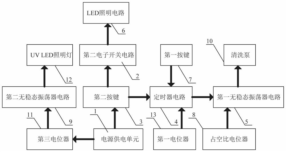
[0023] A control circuit of a medical wound cleaning device, such as figure 1As shown, it includes a power supply unit 1, a second electronic switch circuit 2, a second button 3, a timer circuit 4, a first astable oscillator circuit 5, an LED lighting circuit 6, a first button 7, and a duty cycle Potentiometer 8, cleaning pump 10 and first potentiometer 13, the input end of the second electronic switch circuit 2 is connected to the second button 3, the output end of the second electronic switch circuit 2 is connected to the input of the LED lighting circuit 6 terminal connection, the second button 3 is connected to the input terminal of the timer circuit 4, the input terminal of the timer circuit 4 is connected to the first button 7, and the input terminal of the timer circuit 4 is connected to the first potentiometer 13 connected, the output end of the timer circuit 4 is connected to the input end of the first astable oscillator circuit 5, and the input end of the first astable
Embodiment 2
[0026] On the basis of Example 1, such as figure 1 As shown, it also includes a second astable oscillator circuit 9, a third potentiometer 11 and a UVLED lighting lamp 12, the third potentiometer 11 is connected to the input end of the second astable oscillator circuit 9, so The output terminal of the second astable oscillator circuit 9 is connected to the UVLED lighting lamp 12, and the power supply unit 1 supplies power for the second astable oscillator circuit 9, the third potentiometer 11 and the UVLED lighting lamp 12.
[0027] After the control circuit of the medical wound cleaning device is powered on, the second astable oscillator circuit 9 controls the UVLED lighting lamp 12 to work, and the UVLED lighting lamp 12 emits ultraviolet rays to disinfect the wound and accelerate the wound healing speed. The medical staff can pass the third The potentiometer 11 adjusts the power of the UVLED illuminating lamp 12, and then adjusts the brightness of the UVLED illuminating lamp 1
Embodiment 3
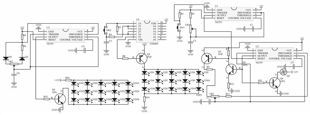
[0029] A control circuit of a medical wound cleaning device, such as figure 2 As shown, the second electronic switch circuit 2 includes six inverter circuits CD4069-U4, tact switch SW2, capacitor C3, resistor R8 and triode Q2, and pin 7 of the six inverter circuit CD4069-U4 is grounded , pin 14 of the six-inverter circuit CD4069-U4 is connected to +5V, pin 1 of the six-inverter circuit CD4069-U4 is connected in series with the tact switch SW2 and capacitor C3, and the other end of the capacitor C3 is grounded, so Pin 1 of the six-inverter circuit CD4069-U4 is connected to one end of the resistor R3, the other end of the resistor R3 is connected to pin 5 of the six-inverter circuit CD4069-U4, and the six-inverter circuit CD4069-U4 The pin 2 of the six-inverter circuit CD4069-U4 is connected to one end of the resistor R4, and the other end of the resistor R4 is connected to the middle point of the series connection between the tact switch SW2 and the capacitor C3, and the pin 2 of
PUM
 Abstract
Description
Claims
Application Information
 - R&D Engineer
- R&D Manager
- IP Professional
- Industry Leading Data Capabilities
- Powerful AI technology
- Patent DNA Extraction
Browse by: Latest US Patents, China's latest patents, Technical Efficacy Thesaurus, Application Domain, Technology Topic.
© 2024 PatSnap. All rights reserved.Legal|Privacy policy|Modern Slavery Act Transparency Statement|Sitemap