Reflective type eyepiece optical system and head-mounted near-eye display device
An optical system and reflective technology, applied in the optical field, can solve the problems of heavy optical structure, insufficient field of view, and low image quality, and achieve the effects of reducing cost and weight, improving optical indicators, and increasing possibilities
- Summary
- Abstract
- Description
- Claims
- Application Information
AI Technical Summary
Problems solved by technology
Method used
Image

Examples
no. 1 example
[0131] The eyepiece design data of the first embodiment are shown in Table 1 below:
[0132]
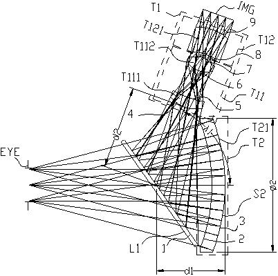
[0133] attached figure 1 It is the optical path diagram of the eyepiece optical system of the first embodiment, including the first lens group T1, and the first optical element L1 and the second lens group T2 for transmitting and reflecting light from the micro image display IMG; the second lens group T2 Contains an optical reflection surface S2, and the optical reflection surface S2 is the optical surface farthest from the observation side of the human eye in the second lens group T2; the optical reflection surface S2 is concave to the viewing direction of the human eye; the first optical element L1 will pass through the first The light refracted by the lens group T1 is reflected to the second lens group T2, and then the light refracted, reflected and refracted by the second lens group T2 is transmitted to the human eye EYE.
[0134] Wherein the first lens group T1 includes the fir
no. 2 example
[0138] The eyepiece design data of the second embodiment are shown in Table 2 below:
[0139]
[0140] attached Figure 5 It is the optical path structure diagram of the second embodiment, including the first lens group T1, and the first optical element L1 and the second lens group T2 for transmitting and reflecting light from the micro image display IMG; the second lens group T2 includes a The optical reflective surface S2, and the optical reflective surface S2 is the optical surface farthest from the observation side of the human eye in the second lens group T2; the optical reflective surface S2 is concave to the human eye viewing direction; the first optical element L1 will pass through the first lens group The light refracted by T1 is reflected to the second lens group T2, and then the light refracted, reflected and refracted by the second lens group T2 is transmitted to the human eye EYE.
[0141] Wherein the first lens group T1 includes the first sub-lens group T11 and
no. 3 example
[0145] The eyepiece design data of the third embodiment are shown in Table 3 below:
[0146]
[0147] attached Figure 9 It is the optical path structure diagram of the third embodiment, including the first lens group T1, and the first optical element L1 and the second lens group T2 for transmitting and reflecting light from the micro image display IMG; the second lens group T2 includes a The optical reflective surface S2, and the optical reflective surface S2 is the optical surface farthest from the observation side of the human eye in the second lens group T2; the optical reflective surface S2 is concave to the human eye viewing direction; the first optical element L1 will pass through the first lens group The light refracted by T1 is reflected to the second lens group T2, and then the light refracted, reflected and refracted by the second lens group T2 is transmitted to the human eye EYE.
[0148]Wherein the first lens group T1 includes the first sub-lens group T11 and the
PUM
 Abstract
Description
Claims
Application Information
 - R&D Engineer
- R&D Manager
- IP Professional
- Industry Leading Data Capabilities
- Powerful AI technology
- Patent DNA Extraction
Browse by: Latest US Patents, China's latest patents, Technical Efficacy Thesaurus, Application Domain, Technology Topic.
© 2024 PatSnap. All rights reserved.Legal|Privacy policy|Modern Slavery Act Transparency Statement|Sitemap