Wire harness separation system and separation method thereof

A technology for separating systems and wiring harnesses, applied in lines/collector components, electrical components, circuits, etc., can solve the problems of high labor costs and low work efficiency, and achieve the goals of improving work efficiency, ensuring consistency, and saving labor costs Effect

Pending Publication Date: 2021-10-15
长光(滁州)高端智能装备研究院
View PDF0 Cites 0 Cited by
  • Summary
  • Abstract
  • Description
  • Claims
  • Application Information

AI Technical Summary

Problems solved by technology

At present, the separation method of some wire harnesses is usually separated manually. The manual separa

Method used


Image

  • Wire harness separation system and separation method thereof
  • Wire harness separation system and separation method thereof
  • Wire harness separation system and separation method thereof

Examples


Embodiment Construction

[0029] Hereinafter, embodiments of the present invention will be described with reference to the accompanying drawings. In the following description, the same blocks are denoted by the same reference numerals. With the same reference numerals, their names and functions are also the same. Therefore, its detailed description will not be repeated.

[0030] In order to make the object, technical solution and advantages of the present invention clearer, the present invention will be further described in detail below in conjunction with the accompanying drawings and specific embodiments. It should be understood that the specific embodiments described here are only used to explain the present invention, but not to limit the present invention.

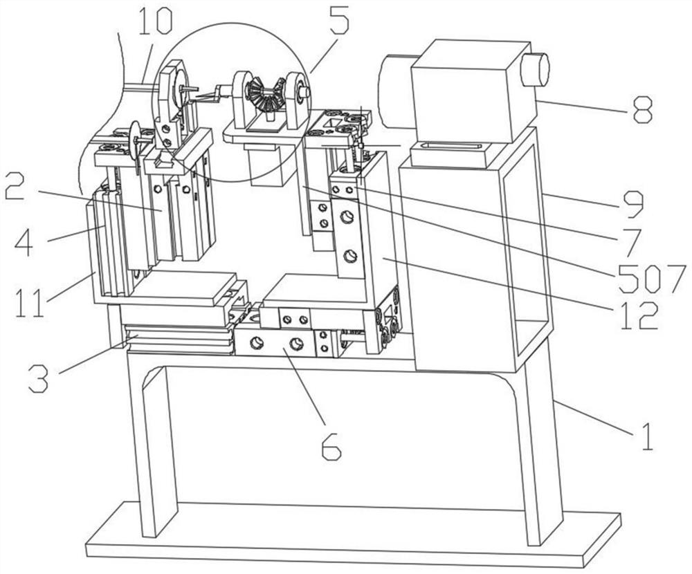
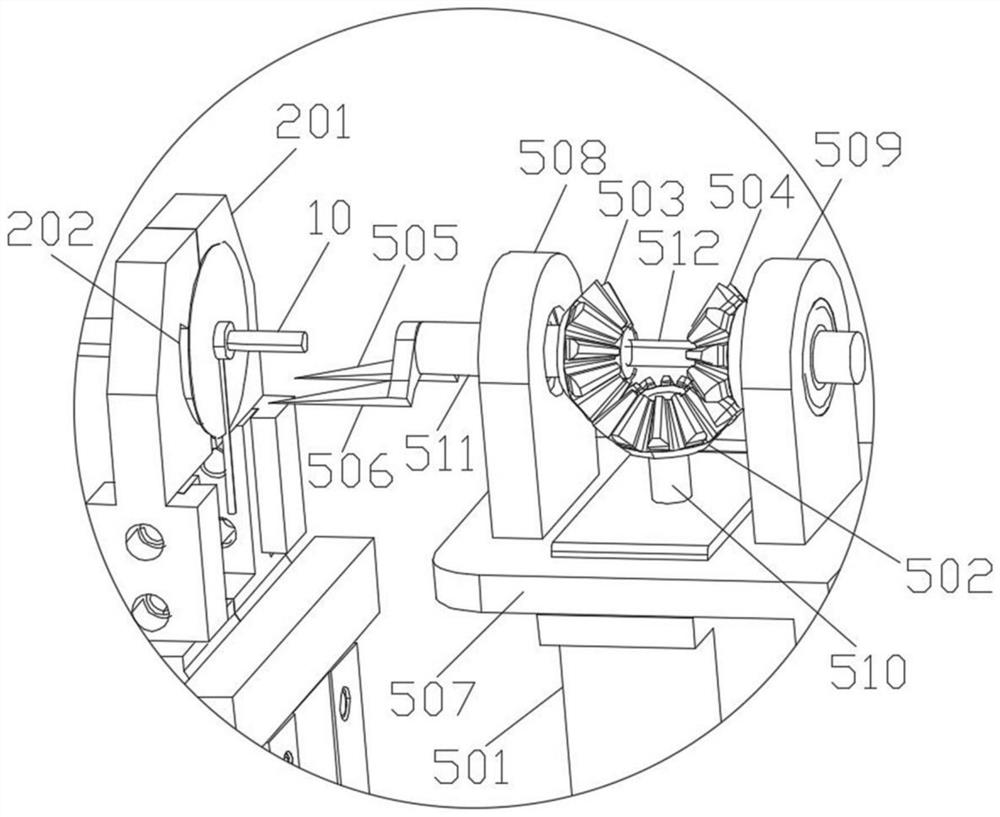
[0031] figure 1 with figure 2 The overall structure and partial enlarged structure of the wire harness separating system provided according to the embodiment of the present invention are respectively shown.

[0032] Such as figure 1 with


PUM


Abstract

The invention provides a wire harness separation system and a separation method thereof. The system comprises a base frame, a clamp transverse movement driving assembly and a wire harness transverse movement driving assembly are fixed to the base frame, a clamp longitudinal movement driving assembly is fixed to the clamp transverse movement driving assembly, and a wire harness clamp is fixed to the clamp longitudinal movement driving assembly and is used for clamping a wire harness, so that the flattened part of the wire harness abuts against the wire harness clamp. A wire harness longitudinal movement driving assembly is fixed to the wire harness transverse movement driving assembly, and a wire harness separation mechanism is fixed to the wire harness longitudinal movement driving assembly and is used for being inserted into the flattened part of the wire harness and clamping a part of the flattened part of the wire harness. Compared with a traditional manual separation mode, the automatic separation of the wire harnesses can be realized, so that the labor cost is saved, the working efficiency is improved, and the consistency of products is ensured.

Description


Claims


Application Information

Patent Timeline
Owner 长光(滁州)高端智能装备研究院
Why Eureka
Try Eureka