Single-polarization low-optical-noise space micromirror coupling system and digital signal processing system

A space micromirror and coupling system technology, applied in the coupling of optical waveguides, optics, optical components, etc., can solve the problems of optical noise interference and large loss, reduce coupling loss, suppress polarization noise, and suppress optical Kerr effect of noise

Pending Publication Date: 2021-10-29
ZHEJIANG UNIV
View PDF9 Cites 2 Cited by
  • Summary
  • Abstract
  • Description
  • Claims
  • Application Information

AI Technical Summary

Benefits of technology

This patented technology allows for better performance at detecting small rotation rates on an optofluidic device called this type of sensor. It uses special materials made up of tiny parts arranged regularly around one or more fibers inside another material like silicon dioxide (SiO2). These structures help reduce interference signals when they are rotating about their axis. They also allow certain types of waves to pass through without losing much energy due to its specific properties such as circularly symmetric structure. Overall, these technical improvements improve the accuracy and efficiency of sensors used in navigation systems.

Problems solved by technology

This patented describes an improved method called HCFO (Heterotropic Cool Fluorescence) technology used with optofluidic devices like laser scanning microelectronics or atomic clocks. However, current methods have limitations due to factors including optically induced errors from other components within the device's environment.

Method used


Image

  • Single-polarization low-optical-noise space micromirror coupling system and digital signal processing system
  • Single-polarization low-optical-noise space micromirror coupling system and digital signal processing system
  • Single-polarization low-optical-noise space micromirror coupling system and digital signal processing system

Examples


Embodiment 1

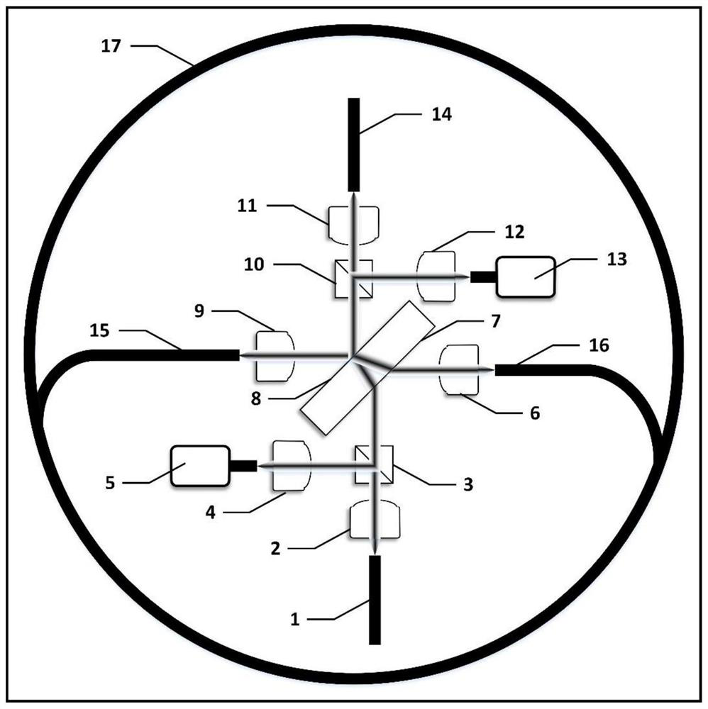
[0025] figure 1 It is a schematic structural diagram of a single polarization low optical noise spatial micromirror coupling system provided by an embodiment of the present invention. The low optical noise spatial coupling system includes a first polarization-maintaining fiber interface 1, a first aspheric lens 2, a first beam splitter Mirror 3, second aspheric lens 4, first photodetector 5, third aspheric lens 6, plane beam splitter, fourth aspheric lens 9, second beam splitter 10, fifth aspheric lens 11, the first Six aspheric lenses 12 , a second photodetector 13 , a second polarization-maintaining fiber interface 14 , a first hollow-core photonic crystal fiber interface 15 , a second hollow-core photonic crystal fiber interface 16 , and a hollow-core photonic crystal fiber resonant cavity 17 . Among them, the diameter of the six groups of aspheric lenses is 4.7mm, the focal length is 6.2mm, the splitting ratio of the two groups of beam mirrors is 0.9, and the reflection coeff

Embodiment 2

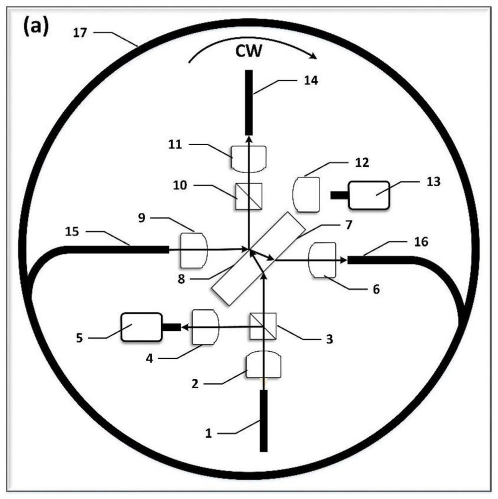
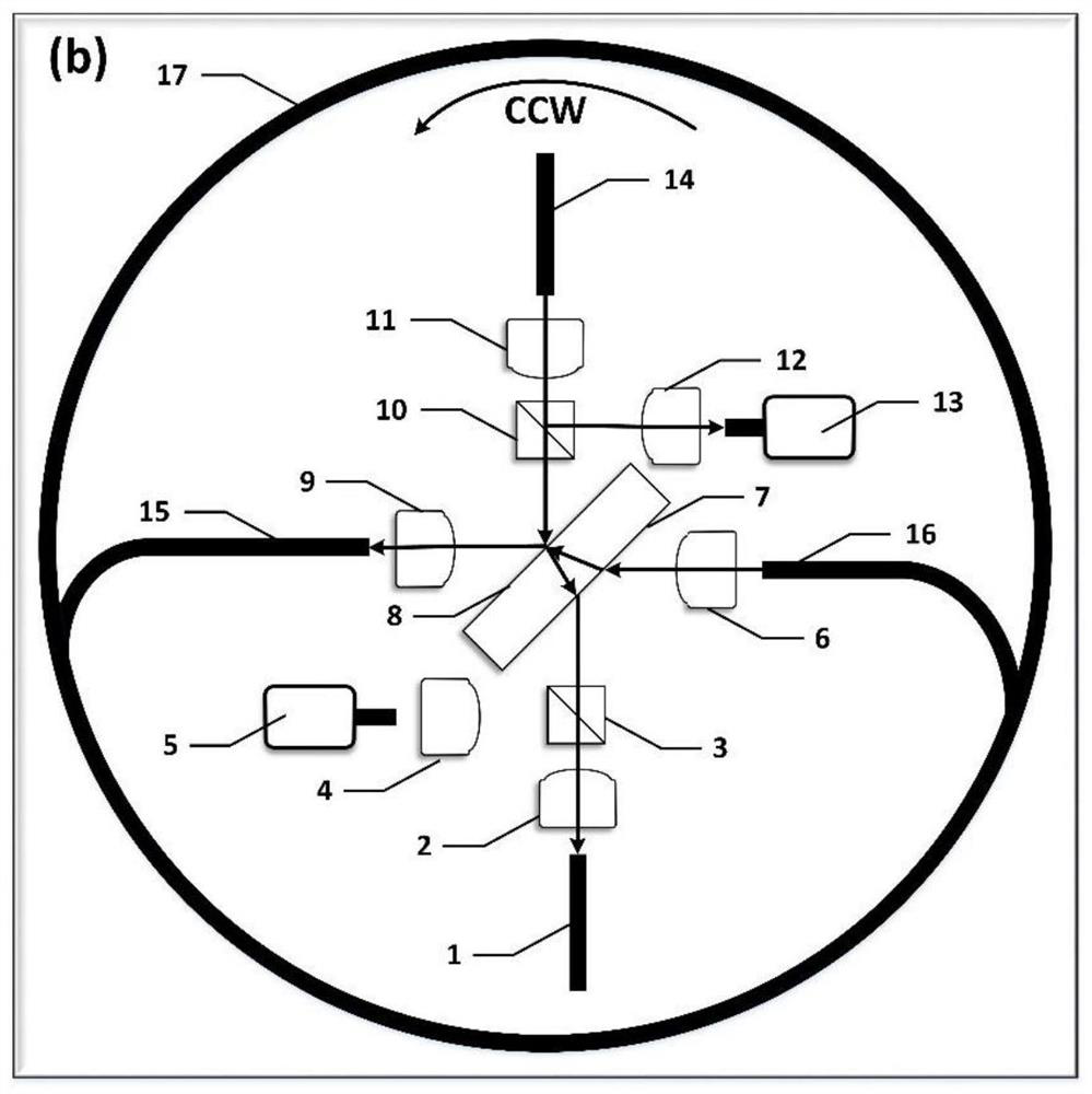
[0031] This embodiment provides a digital signal processing system of a hollow-core photonic crystal fiber gyroscope, the method is based on the low optical noise spatial coupling system described in Embodiment 1, such as Figure 4 As shown, including the tunable laser Tunable Laser, the light emitted by the tunable laser Tunable Laser passes through the phase modulator PM0 and then is split by the signal beam splitter C1 to obtain the second clockwise CW light and the second counterclockwise CCW The second clockwise CW light enters the phase modulator PM2, the intensity modulator IM2, the optical fiber circulator C3, and the polarization-maintaining optical fiber interface PMF1 (corresponding to figure 1 In the first polarization-maintaining fiber interface 1), then through figure 1 The shown spatial coupling system enters the hollow-core photonic crystal resonator 17, and the multi-beam interference results from the polarization-maintaining fiber interface PMF2 (corresponding t


PUM

PropertyMeasurementUnit
Thicknessaaaaaaaaaa

Abstract

The invention discloses a single-polarization low-optical-noise space micromirror coupling system and a digital signal processing system. An optical signal is input from a first polarization maintaining optical fiber interface and sequentially passes through a first aspherical lens, a first spectroscope, the lower surface of a plane beam splitter and the upper surface of the plane beam splitter; a part of the light beam is transmitted and output to a second spectroscope and a fifth aspheric lens, and a part of the light beam is reflected to a third aspheric lens and is coupled into a hollow-core photonic crystal fiber resonant cavity through a second hollow-core photonic crystal fiber interface; after being transmitted for a circle in the hollow-core photonic crystal fiber resonant cavity, the light beams are emitted from the first hollow-core photonic crystal fiber interface and pass through the upper surfaces of the fourth aspherical lens and the plane beam splitter, and part of the light beams are directly transmitted to enter the hollow-core photonic crystal fiber resonant cavity again; and the other part of the light beam is reflected to the second spectroscope and the fifth aspherical lens again to form multi-beam interference, and is output through the second polarization-maintaining optical fiber interface to form a clockwise light path, otherwise, the light path is an anticlockwise light path.

Description


Claims


Application Information

Patent Timeline
Owner ZHEJIANG UNIV
Why Eureka
Try Eureka