Novel fabricated steel-concrete combined steel plate beam

A prefabricated, concrete technology, applied in the direction of bridges, bridge parts, bridge materials, etc., can solve the problems of large maintenance workload, complicated construction, complicated structure, etc., and achieve the effect of improving durability, good landscape effect, and simplifying structure.

Pending Publication Date: 2021-11-05
SHANGHAI URBAN CONSTR DESIGN RES INST GRP CO LTD
View PDF8 Cites 0 Cited by
  • Summary
  • Abstract
  • Description
  • Claims
  • Application Information

AI Technical Summary

Benefits of technology

This patented design allows for easier assembly without causing stress cracks on the roof or other parts of the building's infrastructure due to its support structures. It also includes designs with different types of reinforcement materials like cables (strengthened bars) inside it to improve strength while reducing weight compared to traditional methods such as weldings. Overall, this technology helps maintain better quality buildings over time through improved structural integrity and reduced costs associated therewith.

Problems solved by technology

Technological Problem addressed in this patented text includes three main issues with current design methods for reinforceable steel- concret composite slabs used in building constructions such as piows or bridges. These challenges include prevention from cracks caused by tensile stress due to environmental factors like rainfall, rust damage, etc., stable performance over time without adding extra weight that can make maintenance more complex than necessary, complexity associated with multiple beams being installed within each section, and difficulty ensuring proper alignment when installing posts after they've been put into place.

Method used


Image

  • Novel fabricated steel-concrete combined steel plate beam
  • Novel fabricated steel-concrete combined steel plate beam
  • Novel fabricated steel-concrete combined steel plate beam

Examples


Embodiment

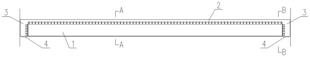
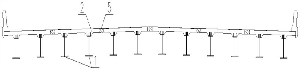
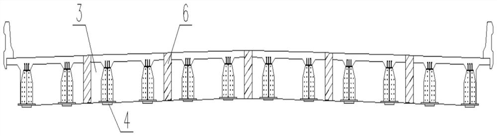
[0028] Such as Figure 1-Figure 5 As shown, a new type of prefabricated steel-concrete composite steel plate girder includes at least one "π"-shaped beam composed of two I-shaped beams 1 and a panel 2, and the end of the "π"-shaped beam is covered with a beam 3. The bottom end of the "π"-shaped beam is provided with a support 4, and the panel wet joint 5 and the beam wet joint 6 formed between the "π"-shaped beams are respectively provided with structural stress ribs, and the "π"-shaped beam is erected on site After that, the panel wet joint 5 and the beam wet joint 6 are poured on site.

[0029] The I-shaped beam 1 is a steel structure, and the panel 2 and the beam 3 are both concrete structures.

[0030] The beam 3 is outsourced on the outside of the I-shaped beam 1 .

[0031] The support 4 is arranged at the bottom end of the I-shaped beam 1 .

[0032] The number of "π"-shaped beams is determined by the width of the road. A single "π"-shaped beam is made by processing two s


PUM


Abstract

The invention discloses a novel fabricated steel-concrete combined steel plate beam which at least comprises a pi-shaped beam composed of two I-shaped beams and a panel, the end of the pi-shaped beam is wrapped with a cross beam, a support is arranged at the bottom end of the pi-shaped beam, and structural stress ribs are respectively arranged in a panel wet joint and a cross beam wet joint formed between the pi-shaped beams. The simply-supported structure system of the pi-shaped beam is adopted, construction at the pier top is simplified, the problem that a bridge deck slab at the pier top is pulled to crack is solved, and the structural durability is improved; the two I-shaped beams and the panel are designed to be pi-shaped beams, and the two supports are arranged so that the stability problem in the mounting process is solved; transverse stiffeners in the midspan steel cross beam and the steel beam web in the prior art are abandoned, the structure is greatly simplified, the landscape effect is good, maintenance is easy, and the workload is small.

Description


Claims


Application Information

Patent Timeline
Owner SHANGHAI URBAN CONSTR DESIGN RES INST GRP CO LTD
Why Eureka
Try Eureka