Oil cooling control system of electric drive assembly

A control system and electric drive technology, which is applied in the combination of cooling and arrangement of power plants, electric vehicles, electric power plants, etc., can solve problems such as heavy workload, achieve easy layout, increase feasibility, and reduce calibration workload Effect

Active Publication Date: 2021-11-09
LEADRIVE TECH (SHANGHAI) CO LTD
View PDF6 Cites 0 Cited by
  • Summary
  • Abstract
  • Description
  • Claims
  • Application Information

AI Technical Summary

Problems solved by technology

For OEMs, a large amount of calibration workload needs to be generated, and when using electric drive assembli

Method used


Image

  • Oil cooling control system of electric drive assembly

Examples


Embodiment Construction

[0040] The advantages of the present invention will be further elaborated below in conjunction with the accompanying drawings and specific embodiments.

[0041] Reference will now be made in detail to the exemplary embodiments, examples of which are illustrated in the accompanying drawings. When the following description refers to the accompanying drawings, the same numerals in different drawings refer to the same or similar elements unless otherwise indicated. The implementations described in the following exemplary examples do not represent all implementations consistent with the present disclosure. Rather, they are merely examples of apparatuses and methods consistent with aspects of the present disclosure as recited in the appended claims.

[0042] The terminology used in the present disclosure is for the purpose of describing particular embodiments only, and is not intended to limit the present disclosure. As used in this disclosure and the appended claims, the singular fo


PUM


Abstract

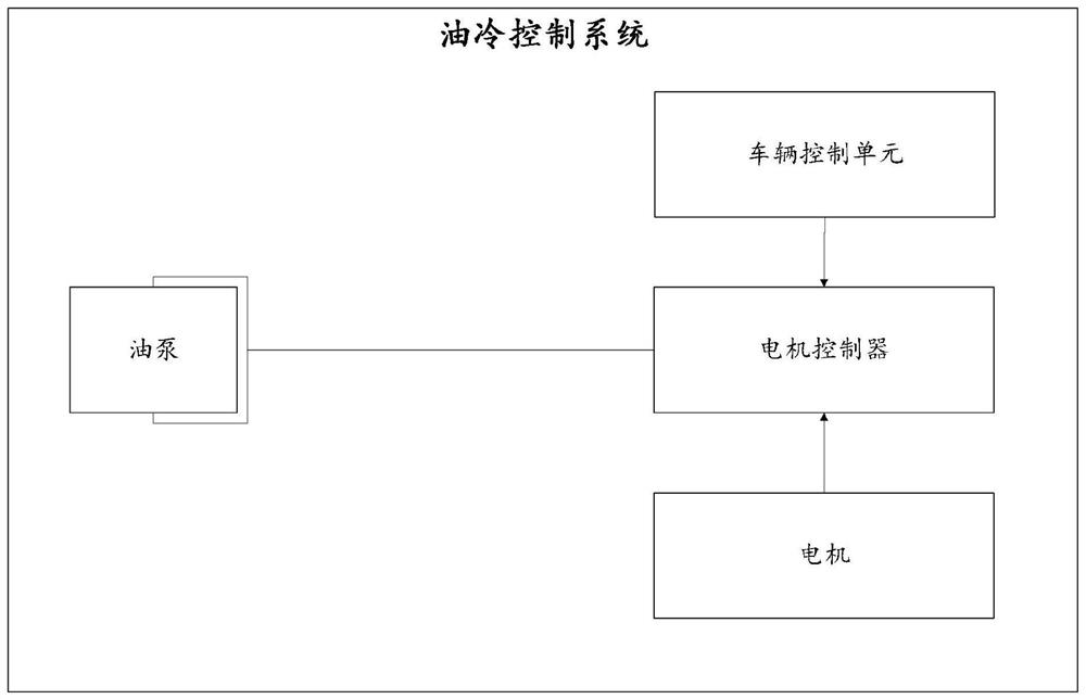
The invention provides an oil cooling control system of an electric drive assembly. The oil cooling control system comprises an oil pump and a motor controller, and the oil cooling control system further comprises the motor controller which is in communication connection and electric connection with the oil pump so as to provide electric energy for the oil pump; a vehicle control unit which is in communication connection with the motor controller and sends driving response information to the motor controller; and a motor which is in communication connection with the motor controller and sends motor state information to the motor controller. The motor controller sends a control instruction to the oil pump based on the driving response information and the motor state information, and the oil pump supplies oil to the motor for cooling based on the control instruction. After the technical scheme is used, the electric drive assembly can define the optimal control policy according to internal bottom layer data and algorithms, and the whole vehicle does not need to calibrate an oil cooling system.

Description


Claims


Application Information

Patent Timeline
Owner LEADRIVE TECH (SHANGHAI) CO LTD
Why Eureka
Try Eureka