Detection function verification method and device, equipment and medium

A functional verification and equipment technology, applied in the field of image processing, can solve the problem of high cost and achieve the effect of saving verification cost

Pending Publication Date: 2021-11-23
昆山丘钛光电科技有限公司
View PDF0 Cites 0 Cited by
  • Summary
  • Abstract
  • Description
  • Claims
  • Application Information

AI Technical Summary

Benefits of technology

This technology allows for accurate analysis of image sensor (IS) readings by analyzing lens distortion caused by changes made during imaging due to temperature fluctuations over time. By accurately determining which components are affected by these variations, it becomes possible to prevent issues such as reduced sensitivity and increased noise levels that may occur when capturing high definition images with low light level cameras. Additionally, this technology helps reduce costs associated with testing devices used to verify their accuracy.

Problems solved by technology

Technological Problem: In order to reduce manufacturing costs while maintaining quality control during production processes, cameras are tested with different methods depending on their specific characteristics or design requirements. However, current techniques require expensive hardware components like sensors and test fixtures, leading to increased testing times. There also remains room for improvement over existing approaches due to limitations associated with detecting incorrect light levels from certain types of lenses.

Method used


Image

  • Detection function verification method and device, equipment and medium
  • Detection function verification method and device, equipment and medium
  • Detection function verification method and device, equipment and medium

Examples


Embodiment Construction

[0042] The embodiment of the present application solves the technical problem of the high cost of verifying the detection capability of the detection equipment for detecting LSC data in the prior art by providing a detection function verification method.

[0043] The technical solution of the embodiment of the present application is to solve the above-mentioned technical problems, and the general idea is as follows:

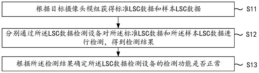
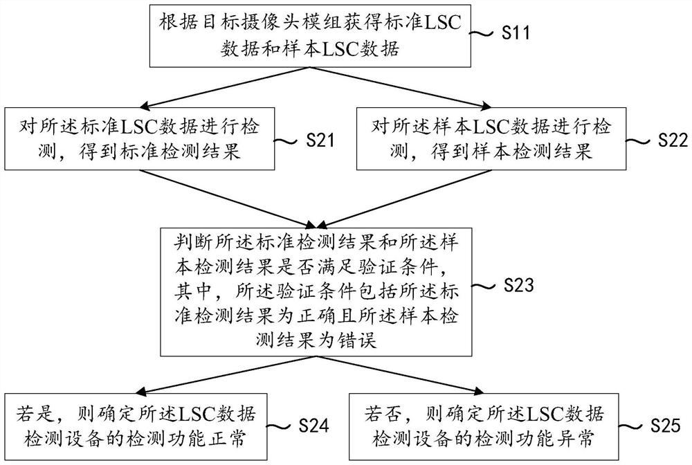
[0044] A detection function verification method applied to LSC data detection equipment, the method comprising: obtaining standard LSC data and sample LSC data according to a target camera module; respectively detecting the standard LSC data and sample LSC data through the LSC data detection equipment to obtain the detection Result: Determine whether the detection function of the LSC data detection equipment is normal according to the detection result.

[0045] In this embodiment, according to the LSC data in the target camera module, standard LSC data in the correc


PUM


Abstract

The invention discloses a detection function verification method and device, equipment and a medium, which are applied to LSC data detection equipment, and the method comprises the following steps: obtaining standard LSC data and sample LSC data by a target camera module; detecting the standard LSC data and the sample LSC data through LSC data detection equipment, and obtaining detection results; and determining whether the detection function of the LSC data detection equipment is normal or not according to the detection results. According to the method and the device, the standard LSC data with the correct sequence and the sample LSC data with the wrong sequence can be obtained through simulation on the premise of avoiding manufacturing wrong burning software and defective product modules; and the LSC data detection equipment is used for detecting the obtained standard LSC data and the sample LSC data to obtain the detection result, and whether the detection function of the LSC data detection equipment is normal or not can be determined according to the detection result, so that the verification cost of the detection equipment can be saved.

Description


Claims


Application Information

Patent Timeline
Owner 昆山丘钛光电科技有限公司
Why Eureka
Try Eureka