Flat rail replacement equipment and method

A technology for replacing equipment and replacement methods, which is applied in the direction of lighting and heating equipment, lifting equipment braking devices, and charging processing types, etc. The risk of human crush injury accidents, improved safety, and high replacement efficiency

Pending Publication Date: 2021-12-03
MCC BAOSTEEL TECH SERVICE
View PDF0 Cites 0 Cited by
  • Summary
  • Abstract
  • Description
  • Claims
  • Application Information

AI Technical Summary

Problems solved by technology

[0002] The flat rails of the sintering machine need to be replaced regularly due to wear and tear. The weight of the flat rails is relatively heavy (the length of a single flat rail is about 8m and the weight is about 500kg). The flat rail inside the hood is inconvenient to transport, and the difficulty and workload are relatively large
[0003] When there is no hot air cover, the flat rail can be hoisted directly to the installation position by crane hoi

Method used


Image

  • Flat rail replacement equipment and method
  • Flat rail replacement equipment and method

Examples


Embodiment Construction

[0053] The implementation of the present invention will be illustrated by specific specific examples below, and those skilled in the art can easily understand other advantages and effects of the present invention from the contents disclosed in this specification.

[0054] Please refer to attached picture. It should be noted that the structures, proportions, sizes, etc. shown in the drawings attached to this specification are only used to match the content disclosed in the specification, for those who are familiar with this technology to understand and read, and are not used to limit the implementation of the present invention. Limiting conditions, so there is no technical substantive meaning, any modification of structure, change of proportional relationship or adjustment of size, without affecting the effect and purpose of the present invention, should still fall within the scope of the present invention. The disclosed technical content must be within the scope covered.

[0055


PUM


Abstract

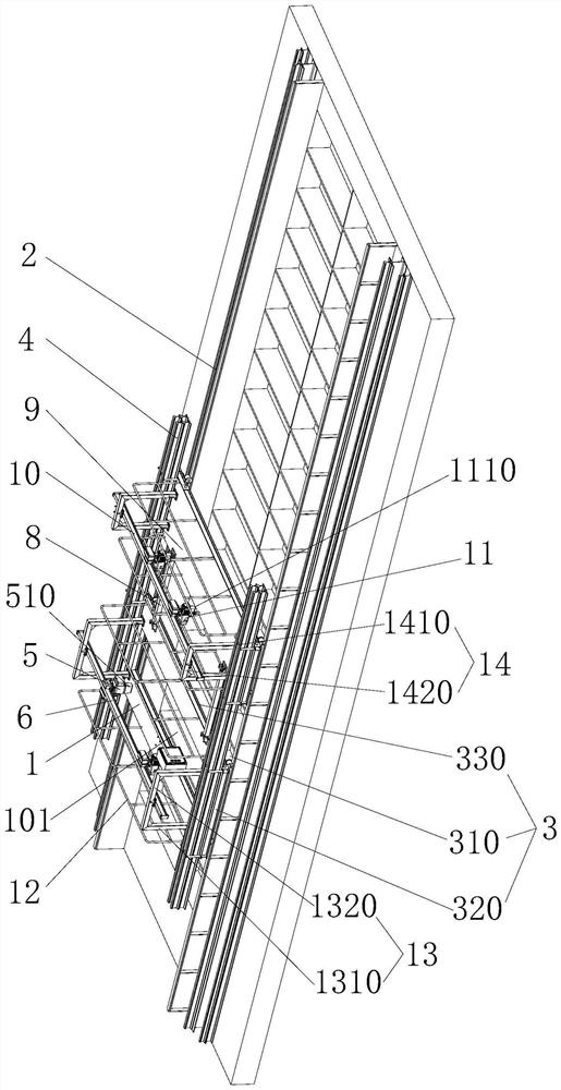
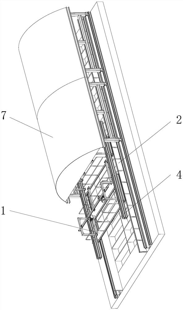
The invention provides flat rail replacement equipment and method.The flat rail replacement equipment comprises a first trolley, a driving device and a first lifting device used for lifting a flat rail, a first bearing beam is erected on the first trolley, and the first bearing beam and a fixed sliding way are arranged in a crossed mode; and the first lifting device is arranged on the first bearing beam and can move along the first bearing beam. The flat rail replacing method comprises the following steps that a driving device drives the first trolley to move to a flat rail to be dismounted in a hot air cover along a fixed sliding way of a sintering machine; the flat rail to be dismantled is dismantled; the disassembled flat rail is hoisted to the first trolley through the first lifting device; a driving device drives the first trolley to move out of the hot air cover along a fixed slideway of the sintering machine; and the disassembled flat rail is lifted away from the first trolley through an on-site travelling crane. According to the flat rail replacement equipment and method, the replacement mode that a plurality of guide chains are used for horizontally replacing and transferring a flat rail to enter and exit the hot air cover in the prior art can be replaced, and the replacement efficiency is higher.

Description


Claims


Application Information

Patent Timeline
Owner MCC BAOSTEEL TECH SERVICE
Why Eureka
Try Eureka