Impeller assembly and washing machine
A technology of washing machine and pulsator, which is applied in the field of washing machine to achieve the effect of preventing splashing, enhancing washing strength and preventing water splashing
- Summary
- Abstract
- Description
- Claims
- Application Information
AI Technical Summary
Problems solved by technology
Method used
Image

Examples
Example Embodiment
[0057] Example 1
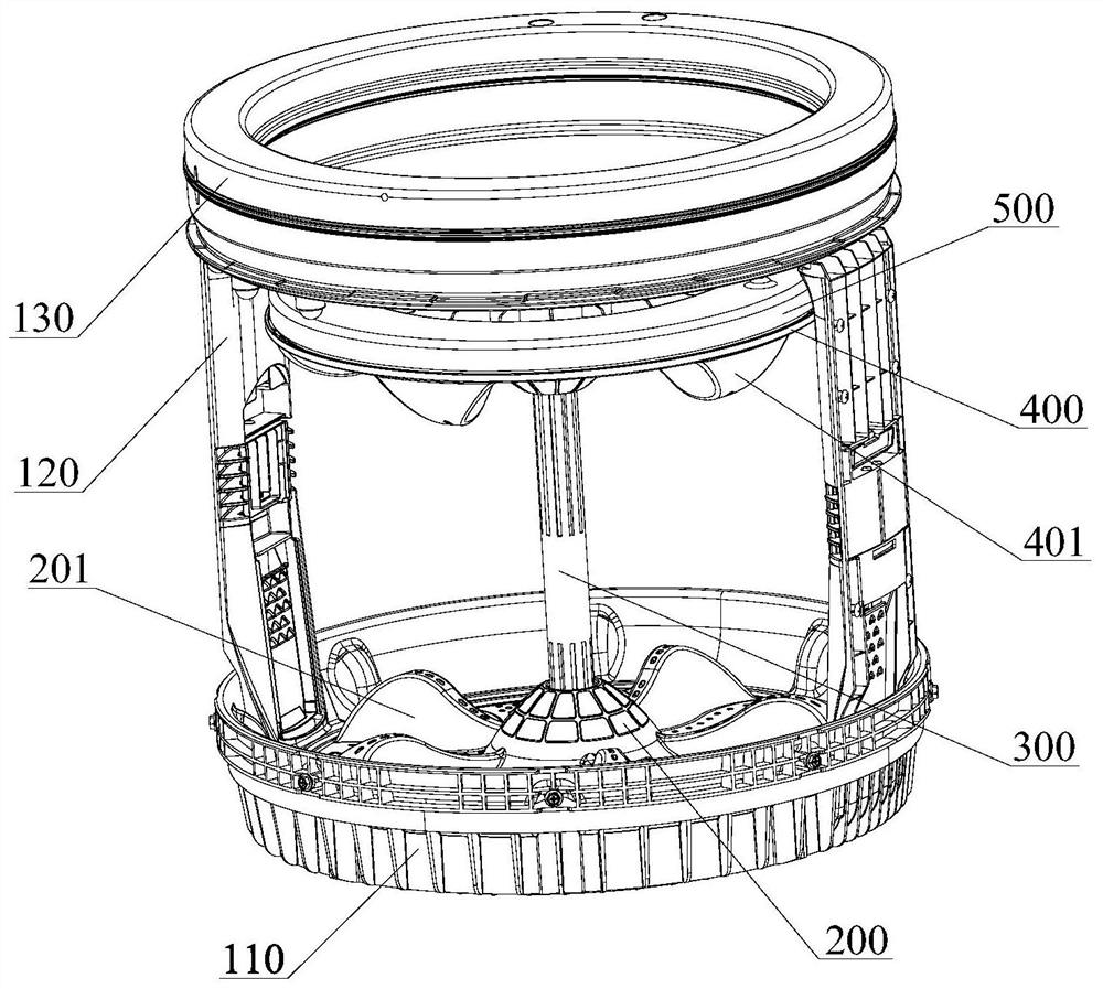
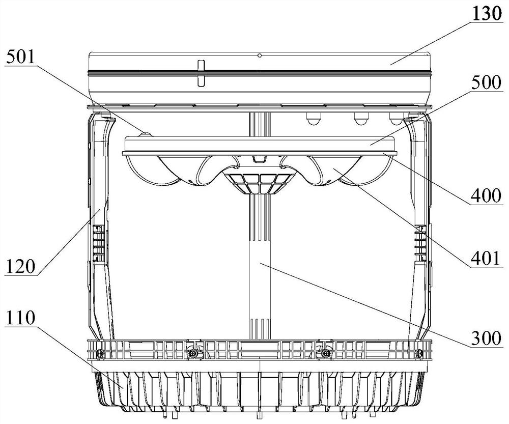
[0058] like Figure 1 to Figure 5 As shown, this embodiment provides a pulsator assembly and a washing machine including the pulsator assembly.
[0059] Specifically, the pulsator assembly includes:
[0060] The first wave wheel 200;
[0061] The second pulsator 400 is arranged above the first pulsator 200;
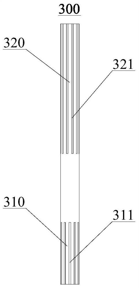
[0062] The connecting piece 300 is used to connect the first pulsator 200 and the second pulsator 400 .
[0063] The second pulsator 400 is mounted on the connecting member 300 in a relatively movable manner, and the second pulsator 400 moves closer to or away from the first pulsator 200 relative to the connecting member 300 .
[0064] The washing machine of this embodiment specifically includes an inner tub, and the above-mentioned pulsator assembly disposed inside the inner tub. Wherein, the first pulsator 200 is rotatably disposed at the bottom of the inner tub.
[0065] In this embodiment, the first stirring ribs 201 are provided on the upper sur
Example Embodiment
[0088] Embodiment 2
[0089] This embodiment is a further limitation of the above-mentioned first embodiment. A limiting device is provided on the connecting portion, and the limiting device is installed above the second pulsator to limit the highest position where the second pulsator can slide.
[0090] During the washing process, especially when the washing speed is high and the weight of the second pulsator is light, the second pulsator may slide up a large distance along the connecting part during the rotation process, causing the second stirring rib to submerge in the water surface. Partially reduced, even completely separated from the washing water, thereby weakening the stirring effect of the washing water, and unable to produce effective friction with the clothes to achieve the ideal washing effect.
[0091] In this embodiment, by disposing a limiting device on the connecting portion that can limit the position of the second pulsator, the highest position that the second
Example Embodiment
[0099] Embodiment 3
[0100] like Figure 1 to Figure 5 As shown, this embodiment is a further limitation of the above-mentioned first embodiment, and the second pulsator 400 is provided with a weight adjusting device that can adjust the weight. The user can adjust the overall weight of the second pulsator 400 by adjusting the weight of the weight adjustment device, especially when the laundry is poorly soaked in water, the second pulsator 400 can have enough weight to completely wash the clothes. Press into the water to make sure the garment is fully soaked.
[0101] At the same time, adjusting the overall weight of the second pulsator 400 to an appropriate level according to different washing speeds and conditions of washing water can also ensure that the second pulsator 400 floats stably at the height of the water surface during the entire washing process, avoiding the occurrence of a second wave If the wheel 400 falls off the water surface too lightly, or sinks to the botto
PUM
 Abstract
Description
Claims
Application Information
 - R&D Engineer
- R&D Manager
- IP Professional
- Industry Leading Data Capabilities
- Powerful AI technology
- Patent DNA Extraction
Browse by: Latest US Patents, China's latest patents, Technical Efficacy Thesaurus, Application Domain, Technology Topic.
© 2024 PatSnap. All rights reserved.Legal|Privacy policy|Modern Slavery Act Transparency Statement|Sitemap