Stirring impeller and apparatus therewith and method therefor

A technology of stirring blade and stirring device, which is applied in the field of stirring device and stirring blade, can solve the problems of inability to stir treatment, fine particles generated by suspension polymerization, small area, etc., and achieve the effect of high cleanliness

Inactive Publication Date: 2003-01-15
KOBELCO ECO-SOLUTIONS CO LTD
View PDF0 Cites 4 Cited by
  • Summary
  • Abstract
  • Description
  • Claims
  • Application Information

AI Technical Summary

Problems solved by technology

As a result, especially in the case of stirring a small-capacity material to be stirred, the area of ​​the blade portion 102a immersed in the material to be stirred is small, resulting in a portion (dead space) where the material to be stirred is stagnant, and sufficient agitation cannot be performed.
[0018] In addition, in the prior art, since stirring is performed under high shear (high power), fine aggregates are generated during emulsion polymerization, and there is a problem that fine particles are generated during suspension polymerization.

Method used


Image

  • Stirring impeller and apparatus therewith and method therefor
  • Stirring impeller and apparatus therewith and method therefor
  • Stirring impeller and apparatus therewith and method therefor

Examples


Example Embodiment

[0042] Hereinafter, embodiments of the present invention will be described with reference to the drawings.

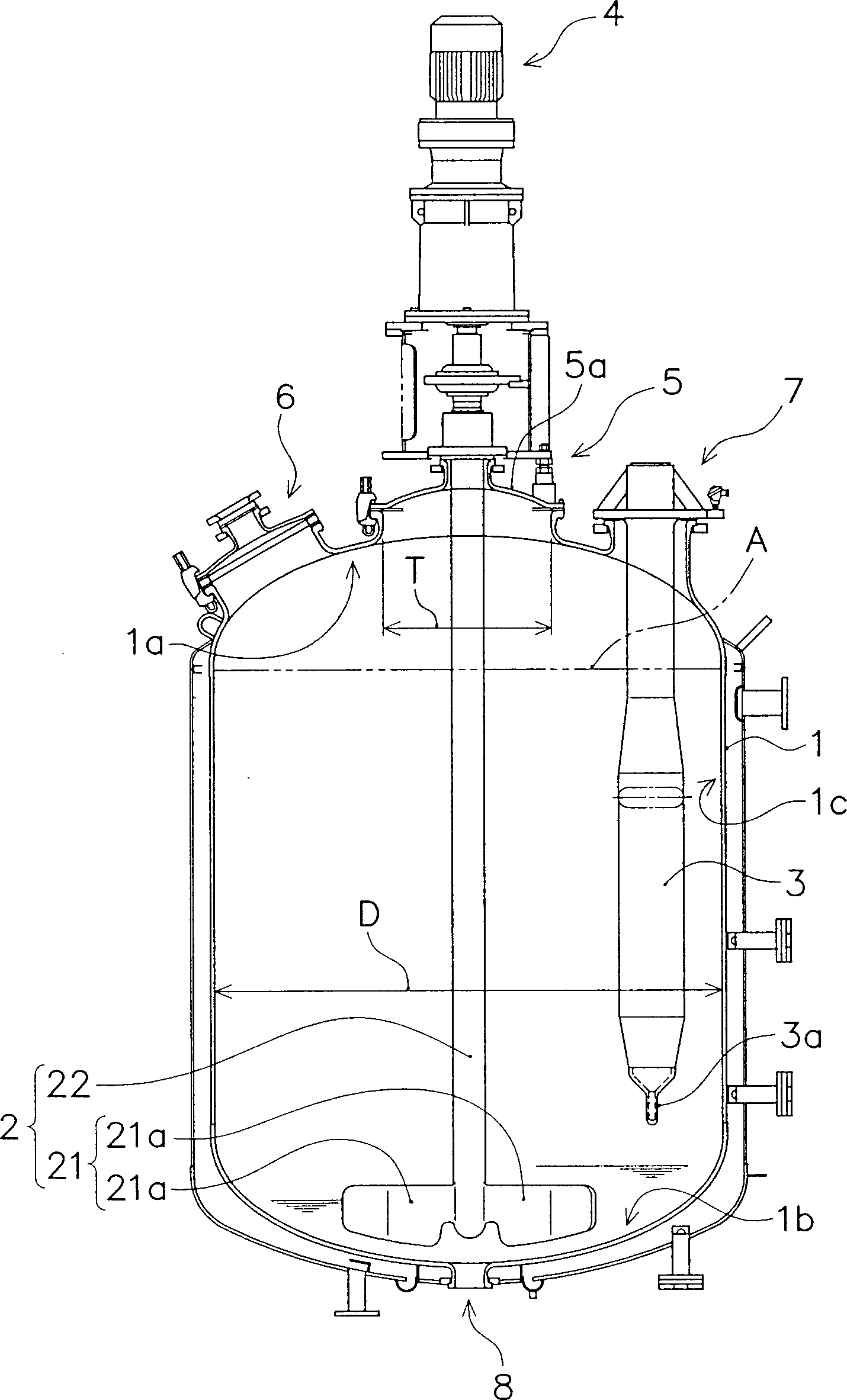
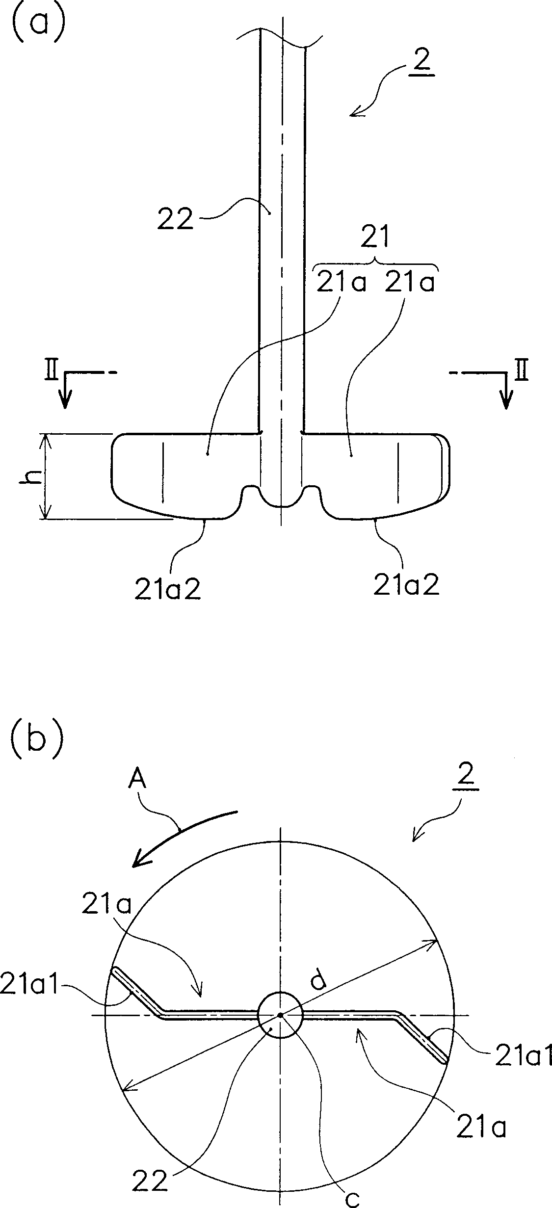
[0043] figure 1 This is a schematic diagram showing a stirring device according to an embodiment of the present invention. The stirring device includes a stirring tank 1 having a vertical cylindrical shape, a stirring blade 2 rotatably installed in the stirring tank 1, a baffle portion 3 fixedly arranged at a predetermined position in the stirring tank 1, and the like. The stirring blade 2 is composed of a blade portion 21 and a stirring shaft 22. The blade portion 21 is composed of two blade configuration portions 21a. The stirring shaft 22 is connected to a driving portion 4 provided at an upper portion outside the stirring tank 1 and driven to rotate.

[0044] The stirring tank 1 has a vertical cylindrical shape as described above, and a stirring blade installation port 5 used to install the stirring blade 2 inside the stirring tank 1 is provided on the top 1a, and used w


PUM


Abstract

A stirring impeller and apparatus therewith and method therefor, wherein, In the stirring blade 2 having a stirring shaft 22 and a blade part 21 comprising a plurality of blade forming parts 21a fitted to the stirring shaft 22, each blade forming part 21a is formed of a plate-like member, an outer end part of each blade forming part 21a is inclined in the direction setting back with respect to the rotational direction of the stirring blade 2, a lower end part of each blade part 21a is formed so as to be along the shape of a bottom surface 1b of the stirring tank 1 having the stirring blade 2 disposed therein, all corner parts of each blade forming part 21a are rounded, and the stirring shaft 22 and the blade part 21 are provided with glass lining.

Description


Claims


Application Information

Patent Timeline
Owner KOBELCO ECO-SOLUTIONS CO LTD
Why Eureka
Try Eureka