Redundancy system, redundancy management method and readable storage medium
A redundancy management and redundancy technology, applied in the field of data transmission, can solve the problems of complex wiring, poor system flexibility, and low bus utilization, and achieve the effect of simplifying wiring complexity, improving speed, and improving bus utilization.
- Summary
- Abstract
- Description
- Claims
- Application Information
AI Technical Summary
Problems solved by technology
Method used
Image

Examples
Example
[0031] First embodiment
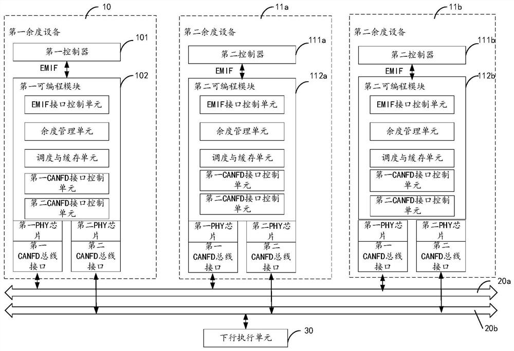
[0032] figure 1 A structural diagram of the remaining system system for the first embodiment of the present application. Such as figure 1 The residual system shown includes 10, 2 second, 2 second pronunciation devices 11a, 11b. In other embodiments, the number of second prolonged device 11 in the remaining system can also be other positive integers, such as 1, 3, 4, and more, etc..
[0033] Such as figure 1 As shown, the first balance device 10 includes a first controller 101, and a first programmable module 102. In an embodiment, the first controller 101 in the first balance device 10 is disposed on different circuit boards, respectively, respectively, respectively, and is connected by a flexible board. In other embodiments, the first programmable module 102 can also be disposed on the main control board at the first controller 101.
[0034] Wherein, the first controller 101 is connected to the first programmable module 102 via the communication interface.
Example
[0050] Second embodiment
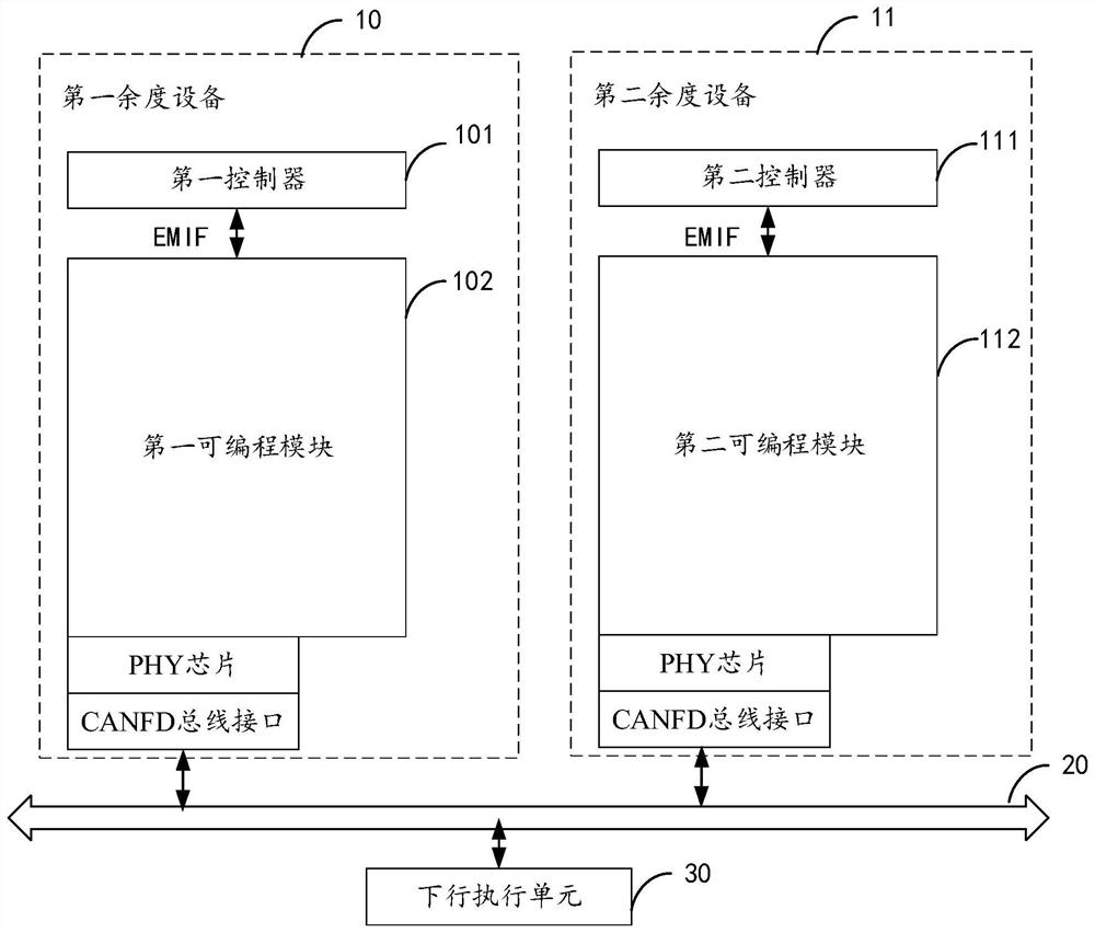
[0051] figure 2 A structural diagram of the remaining system system for the second embodiment of the present application. Such as figure 2 As shown in the present embodiment, the remaining system includes 10, one second priority device 11 of the first balance device.
[0052] Wherein, the first balance device 10 includes a first controller 101, and a first programmable module 102. The first controller 101 is connected to the first programmable module 102 by a communication interface such as an EMIF.
[0053] In an embodiment, the first controller 101 is used to complete the internal residual device such as a speed sensor, an atmospheric data sensor, a displacement sensor, and the like, and the motion control algorithm implementation, state monitoring, and internal overwhellier management. The communication data requires, for example, the first intersection channel data such as cross-transmitted, transmitted to the first programmable module 102 through a se
Example
[0061] Third embodiment
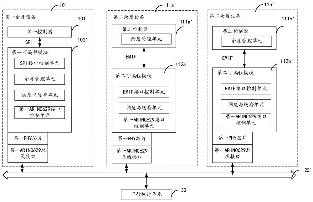
[0062] image 3 A structural diagram of the remaining system system of the third embodiment of the present application. Such as image 3 The residual system shown includes a first balance device 10 ', two second proverbers 11a', 11b '. Such as image 3 The first rational device 10 'shown and if figure 1 The structural and working principle shown are substantially the same, and the first priority apparatus 10 'passes a ArInc629 type of residual bus 20' and the second devices 11a ', 11b'. The first controller 101 'in the first balance device 10' performs data interaction with the first programmable module 102 'in the first programmable module 102'. Such as image 3 The second devices 11A ', 11B' are shown in figure 1 The structural and working principle shown are substantially the same, and the hydraulic management unit is disposed in the second controller 111a ', 111b'.
PUM
 Abstract
Description
Claims
Application Information
 - R&D Engineer
- R&D Manager
- IP Professional
- Industry Leading Data Capabilities
- Powerful AI technology
- Patent DNA Extraction
Browse by: Latest US Patents, China's latest patents, Technical Efficacy Thesaurus, Application Domain, Technology Topic.
© 2024 PatSnap. All rights reserved.Legal|Privacy policy|Modern Slavery Act Transparency Statement|Sitemap