Electronic display reticle for sighting telescope

An electronic display and reticle technology, which is applied in the direction of aiming devices, weapon accessories, offensive equipment, etc., can solve the problems of inability to perform ballistic compensation and large aiming errors, and achieve direct and effective display results, high aiming and shooting accuracy, and display The result is more effective

Pending Publication Date: 2022-01-04
南通智能感知研究院
View PDF1 Cites 0 Cited by
  • Summary
  • Abstract
  • Description
  • Claims
  • Application Information

AI Technical Summary

Benefits of technology

This patented technology allows users to easily see how well they are hitting firearms accurately without having to constantly adjust their gun's settings or look away from them altogether. It uses special plasma displays that show different types of data on varying sizes such as bullet numbers, trajectory details, etc., along with automatic calculations based upon these factors like altitude, airspeed, and distance traveled through space. These technical improvements make it easier for people who want guns to hit fires alive at night time better.

Problems solved by technology

There were technical problem addressed by this patented method: current reticules used for precision shooting cannot achieve both clarity or accuracy due to their design limitations. Additionally they lacked any features like shock sensitivity that allow users to easily hit targets accurately without having excessive effort from trial and error methods.

Method used


Image

  • Electronic display reticle for sighting telescope
  • Electronic display reticle for sighting telescope
  • Electronic display reticle for sighting telescope

Examples


Embodiment

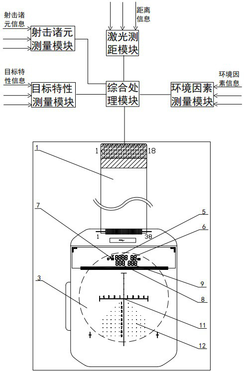
[0024] see Figure 1-2 , this embodiment provides an electronic display reticle for a sight, including an electronic reticle body 4 to display various parameters, and a polarizing sheet is pasted on the top of the electronic reticle body 4 to form an information display area 2. This implementation The electronic reticle body 4 of the example is provided with an information display area 2, wherein the information display area 2 is used to display parameters such as distance measurement value and ballistic compensation amount, and the information display area 2 is the effective light transmission area of ​​the electronic reticle body 4. Aperture, visible light transmittance greater than 90%.

[0025] The information display area 2 in this embodiment includes ranging information 5 , ballistic compensation information 6 , status information 7 , abscissa information 8 , ordinate information 9 and battery power information 10 .

[0026] Wherein, the ranging information 5 of this embod


PUM


Abstract

The invention belongs to the technical field of reticles, and particularly relates to an electronic display reticle for a sighting telescope. According to the electronic display reticle, a polarized light sheet is pasted onto the upper portion of an electronic display reticle body for the sighting telescope to form an information display area used for displaying various parameters, wherein the information display area comprises distance measurement information, the ballistic compensation information is used for displaying errors caused by windage yaw and height of bullets, software automatically calculates the errors and feeds back the ballistic compensation amount, the state information, the abscissa information, the ordinate information and the battery electric quantity information, the ballistic compensation information is added in the information display area, so that the aiming and shooting precision is high, and the display result is more direct and effective; and an effective aiming area is arranged below the electronic reticle body, the effective aiming area is an effective clear aperture, and the visible light transmittance is larger than 90%.

Description


Claims


Application Information

Patent Timeline
Owner 南通智能感知研究院
Why Eureka
Try Eureka