Alternating current-direct current conversion circuit and power conversion device

An AC-DC conversion and conversion circuit technology, which is applied in the output power conversion device, the conversion of DC power input into DC power output, and the conversion of AC power input into DC power output, etc. Problems such as excessive reverse recovery current to achieve the effect of improving drive reliability

Pending Publication Date: 2022-01-25
茂睿芯(深圳)科技有限公司
View PDF0 Cites 0 Cited by
  • Summary
  • Abstract
  • Description
  • Claims
  • Application Information

AI Technical Summary

Benefits of technology

This technology improves how an AC/DC converter works with signals from two different sources: one source for driving power (PWM) while another source uses only energy without being affected). By doing this, it can improve efficiency or reduce heat generation during operation compared to previous designs where both input sides were always driven together.

Problems solved by technology

This patented technical problem addressed by this patents relates to improving the performance of electronic devices that require efficient electrical energy sources such as batteries due to their increasing demand over time. Conventional methods involve utilizing separate components like capacitors and resistors along with other circuitry to achieve better regulation of electricity usage. However these techniques are expensive and increase complexity while also reducing device's overall effectiveness.

Method used


Image

  • Alternating current-direct current conversion circuit and power conversion device
  • Alternating current-direct current conversion circuit and power conversion device
  • Alternating current-direct current conversion circuit and power conversion device

Examples


Embodiment Construction

[0064] In order to make the technical problems, technical solutions and beneficial effects to be solved by the present invention clearer, the present invention will be further described in detail below in conjunction with the accompanying drawings and embodiments. It should be understood that the specific embodiments described here are only used to explain the present invention, not to limit the present invention.

[0065] In addition, the terms "first" and "second" are used for descriptive purposes only, and cannot be interpreted as indicating or implying relative importance or implicitly specifying the quantity of indicated technical features. Thus, a feature defined as "first" and "second" may explicitly or implicitly include one or more of these features. In the description of the present invention, "plurality" means two or more, unless otherwise specifically defined.

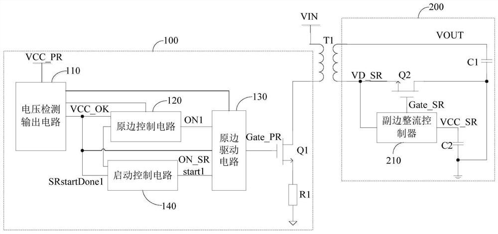
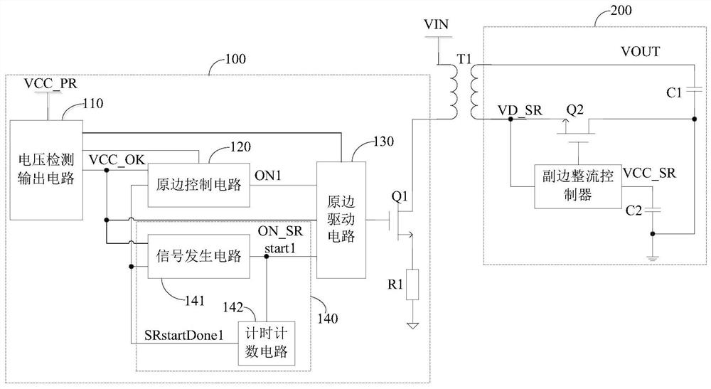
[0066] The first aspect of the embodiments of the present invention provides an AC / DC conversion circuit


PUM


Abstract

The invention is suitable for the technical field of switching power supplies, and particularly relates to an alternating current-direct current conversion circuit and a power conversion device. The alternating current-direct current conversion circuit comprises a transformer, a primary side conversion circuit and a secondary side synchronous rectification circuit, and the primary side conversion circuit comprises a primary side switching tube, a primary side driving circuit, a starting control circuit and a voltage detection output circuit; pre-driving is carried out when a primary side is started, namely, a PWM control signal with a small duty ratio is output to control a primary side switching tube to be switched on and switched off, so that an MOSFET of a secondary side synchronous rectification circuit is ensured to control a primary side control circuit to control a primary side driving circuit to work again after the follow current of a parasitic body diode is attenuated to zero; therefore, the problem that the stress of the secondary side MOSFET is too high due to the reverse recovery current of the diode of the secondary side MOSFET is solved, and the driving reliability is improved.

Description


Claims


Application Information

Patent Timeline
Owner 茂睿芯(深圳)科技有限公司
Why Eureka
Try Eureka