Rare earth particle separation system

A particle separation and rare earth technology, which is applied in the direction of filtration separation, separation method, fixed filter element filter, etc., can solve the problems of reduced filtration efficiency, reduced filtration efficiency, waste of rare earth materials, etc. Improve the separation effect and improve the drying efficiency

Pending Publication Date: 2022-03-15
张清
View PDF0 Cites 0 Cited by
  • Summary
  • Abstract
  • Description
  • Claims
  • Application Information

AI Technical Summary

Benefits of technology

The invention improves the performance of separating mixtures containing solids from liquors or other fluids through filtering techniques that improve their quality. It also includes an apparatus for efficiently removing water vapor while increasing the speed at which they are processed. This results in better purity products with fewer blocked passages compared to traditional methods like filters alone.

Problems solved by technology

Technological Problem: Current methods involve filtering out small amounts (< 1 mm) of valuable metal or mineral residue by utilizing filters made up mostly of fine crystals called rare earth powders. However, current technologies often result in reduced filtrate efficacy over longer periods of operation because some tiny particles may still get trapped inside the pores of the filters themselves. Therefore there needs a new method to efficiently separate rare earth particles without causing damage to them.

Method used


Image

  • Rare earth particle separation system
  • Rare earth particle separation system
  • Rare earth particle separation system

Examples


Embodiment Construction

[0026] The following will clearly and completely describe the technical solutions in the embodiments of the present invention with reference to the accompanying drawings in the embodiments of the present invention. Obviously, the described embodiments are only some, not all, embodiments of the present invention. Based on the embodiments of the present invention, all other embodiments obtained by persons of ordinary skill in the art without making creative efforts belong to the protection scope of the present invention.

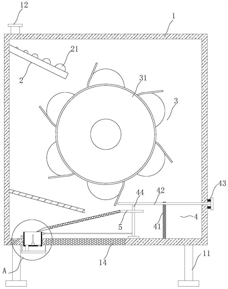
[0027] see Figure 1 to Figure 8 , the present invention provides a technical solution:

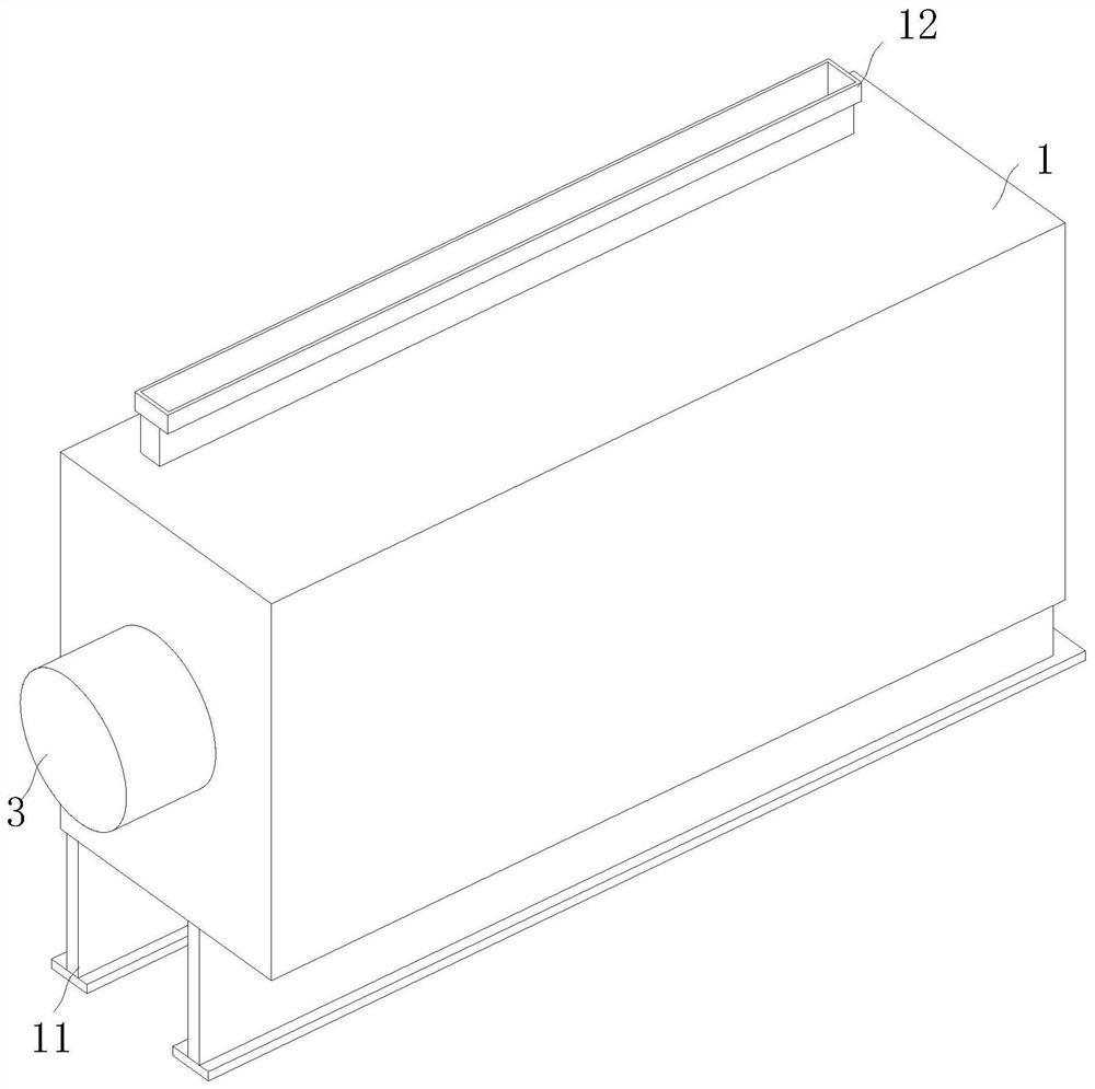
[0028] A rare earth particle separation system such as figure 1 , figure 2 and Figure 7 As shown, it includes an operation frame 1, the operation frame 1 has a rectangular structure design, and the front and rear positions of the outer surface of the lower end of the operation frame 1 are fixedly installed with brackets 11, and the outer surface of the upper end of the


PUM


Abstract

The invention relates to the technical field of rare earth particle extraction, in particular to a rare earth particle separation system which comprises an operation frame, the operation frame is of a rectangular structure design, supports are fixedly installed at the front and rear positions of the outer surface of the lower end of the operation frame, and a feeding hopper is fixedly installed at the position, close to the rear end, of the outer surface of the upper end of the operation frame. A discharging hole is formed in the position, close to the middle of the rear end, of the outer surface of the lower end of the operation frame, a first net plate is embedded in the position, close to the front end of the discharging hole, of the outer surface of the lower end of the operation frame, a flow guide plate is fixedly installed in the position, close to the upper portion of the rear end, of the interior of the operation frame, and a separation mechanism is arranged in the middle of the operation frame. By arranging the separation mechanism, solid particles in a mixture can be conveniently separated from wastewater, the working efficiency is improved, and the flow guide plate is made of a high-toughness metal material. According to the device, separation of rare earth particles and wastewater can be facilitated, the separation efficiency is improved, and meanwhile, the drying efficiency of the rare earth particles is further improved.

Description


Claims


Application Information

Patent Timeline
Owner 张清
Why Eureka
Try Eureka