Interface circuit, signal transmission circuit and electronic equipment

An interface circuit and signal technology, applied in the field of signal transmission, can solve the problems of a large number of pins and restrict the chip area, and achieve the effect of meeting the transmission requirements, saving the number of pins, and saving the area.

Pending Publication Date: 2022-03-15
SHANGHAI YAOHUO MICROELECTRONICS CO LTD
View PDF5 Cites 0 Cited by
  • Summary
  • Abstract
  • Description
  • Claims
  • Application Information

AI Technical Summary

Problems solved by technology

[0004] The invention provides an interface circuit, a signal transmission circuit and electronic equipment to solve the problem that the number of pins is large and the area of ​​the chip is restricted

Method used


Image

  • Interface circuit, signal transmission circuit and electronic equipment
  • Interface circuit, signal transmission circuit and electronic equipment
  • Interface circuit, signal transmission circuit and electronic equipment

Examples


Example Embodiment

[0060] The following will clearly and completely describe the technical solutions in the embodiments of the present invention with reference to the accompanying drawings in the embodiments of the present invention. Obviously, the described embodiments are only some, not all, embodiments of the present invention. Based on the embodiments of the present invention, all other embodiments obtained by persons of ordinary skill in the art without making creative efforts belong to the protection scope of the present invention.

[0061]In the description of the specification of the present invention, it should be understood that the orientation or positional relationship indicated by the terms "upper part", "lower part", "upper end", "lower end", "lower surface" and "upper surface" are based on the drawings The orientations or positional relationships shown are only for the convenience of describing the present invention and simplifying the description, and do not indicate or imply that th


PUM


Abstract

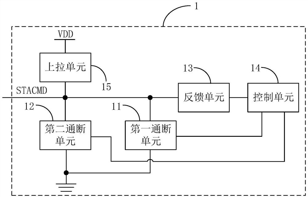
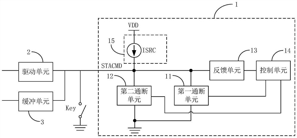
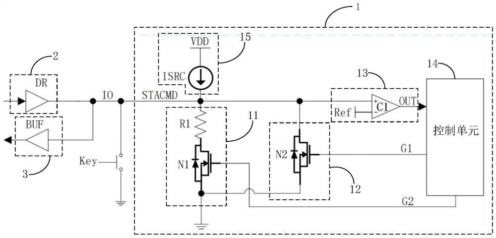
The invention provides an interface circuit, a signal transmission circuit and electronic equipment, and a control unit is configured to control a second on-off unit and a first on-off unit to be turned off when a target pin needs to output a high-level output signal; when the target pin needs to output a low-level logic state signal, the second on-off unit is controlled to be switched on, and the first on-off unit is controlled to be switched off; when the target pin needs to output a low-level digital communication signal, the first on-off unit is controlled to be switched on, and the second on-off unit is controlled to be switched off; the feedback unit can be used for feeding back a first signal to the control module in response to a high-level input signal when the target pin obtains the high-level input signal; and when the target pin obtains a low-level input signal, a second signal is fed back to the control module in response to the low-level input signal.

Description


Claims


Application Information

Patent Timeline
Owner SHANGHAI YAOHUO MICROELECTRONICS CO LTD
Why Eureka
Try Eureka