Optical body system for combining optical paths

An optical and main body technology, applied in the direction of optics, optical components, measuring devices, etc., can solve the problems of reduced measurement accuracy of coordinate measuring instruments, large size of coordinate measuring instruments, laser beam drift, etc.

Pending Publication Date: 2022-04-15
CHOTEST TECH INC
View PDF0 Cites 0 Cited by
  • Summary
  • Abstract
  • Description
  • Claims
  • Application Information

AI Technical Summary

Benefits of technology

The invention provides an improved way for making measurements on objects by utilizing special tools called laser scanners or cameras instead of traditional methods like ruler bars. This makes measurement more accurate and efficient compared with older ways such as mechanical caliprosions.

Problems solved by technology

This patents describes how current designs for precise measurements require that certain components be located within another component's space. However this can lead to increased dimensions when compared with previous versions due to integration issues. Additionally, there may still be some challenges associated with integrating these different types of devices onto each other without affecting their performance.

Method used


Image

  • Optical body system for combining optical paths
  • Optical body system for combining optical paths
  • Optical body system for combining optical paths

Examples


Embodiment Construction

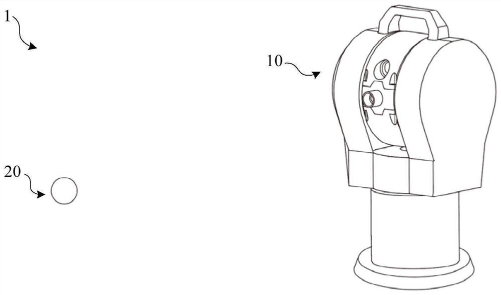
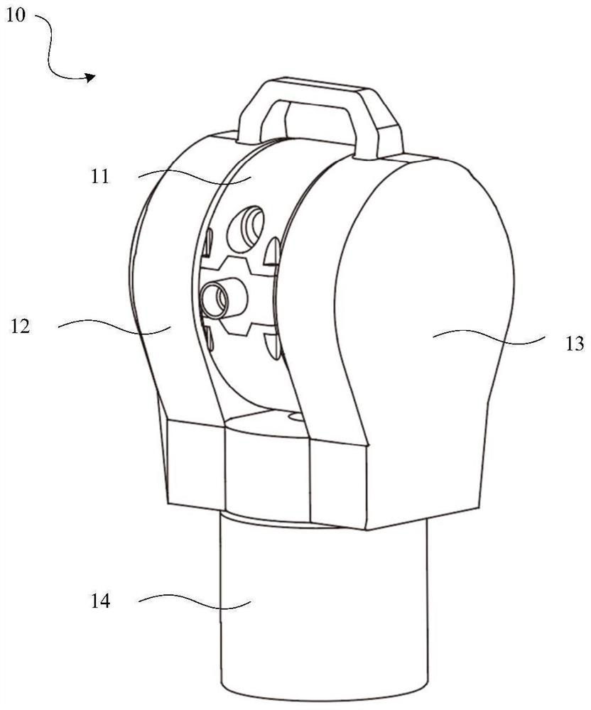
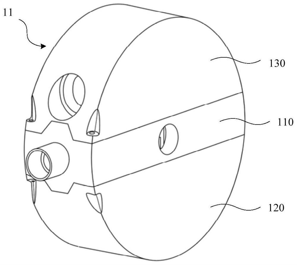
[0025] Hereinafter, preferred embodiments of the present disclosure will be described in detail with reference to the drawings. In the following description, the same reference numerals are given to the same components, and repeated descriptions are omitted. In addition, the drawings are only schematic diagrams, and the ratio of dimensions between components, the shape of components, and the like may be different from the actual ones.

[0026] It should be noted that the terms "comprising" and "having" and any variations thereof in the present disclosure, such as a process, method, system, product or device that includes or has a series of steps or units, are not necessarily limited to the clearly listed instead, may include or have other steps or elements not explicitly listed or inherent to the process, method, product or apparatus.

[0027] In addition, subheadings and the like involved in the following description of the present disclosure are not intended to limit the conte


PUM


Abstract

The invention discloses an optical main body system for combining light paths, which comprises an optical main body seat, distance measuring modules and a light path adjusting module, the distance measuring modules at least comprise a first distance measuring module and a second distance measuring module, the first distance measuring module comprises a first generating unit for generating a first light beam and a first emitting unit for emitting the first light beam, and the second distance measuring module comprises a second emitting unit for emitting the second light beam; the second distance measuring module comprises a second generating unit for generating a second light beam and a second emitting unit for emitting the second light beam; the light path adjusting module comprises a merging unit and a plurality of reflection units, the reflection units comprise a first reflection unit used for reflecting a first light beam to a preset path and a second reflection unit used for reflecting a second light beam to the preset path, and the merging unit is arranged on the preset path; and configured to transmit the first light beam while reflecting the second light beam to combine the first light beam and the second light beam. According to the present disclosure, it is possible to provide an optical body system that optimizes the structural size of a coordinate measuring instrument and simplifies the optical path structure.

Description


Claims


Application Information

Patent Timeline
Owner CHOTEST TECH INC
Why Eureka
Try Eureka