Radar receiving channel calibration method based on monopole crossed loop antenna

A receiving channel and calibration method technology, which is applied in the field of radar receiving channel calibration based on monopole cross-loop antennas, can solve the problems of low efficiency, radar channel characteristic changes, laborious and laborious, etc., and achieve convenient operation, strong autonomy, and measurement high precision effect

Pending Publication Date: 2022-05-13
WUHAN UNIV
View PDF3 Cites 2 Cited by
  • Summary
  • Abstract
  • Description
  • Claims
  • Application Information

AI Technical Summary

Problems solved by technology

When the radar system leaves the factory, although the channel characteristic test can be completed in advance, after the installation is completed on site, the actual radar channel characteristics often change due to the influence of changes in cables, conne

Method used


Image

  • Radar receiving channel calibration method based on monopole crossed loop antenna
  • Radar receiving channel calibration method based on monopole crossed loop antenna
  • Radar receiving channel calibration method based on monopole crossed loop antenna

Examples


no. 2 Embodiment approach specific

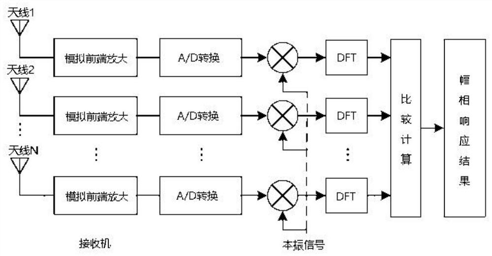
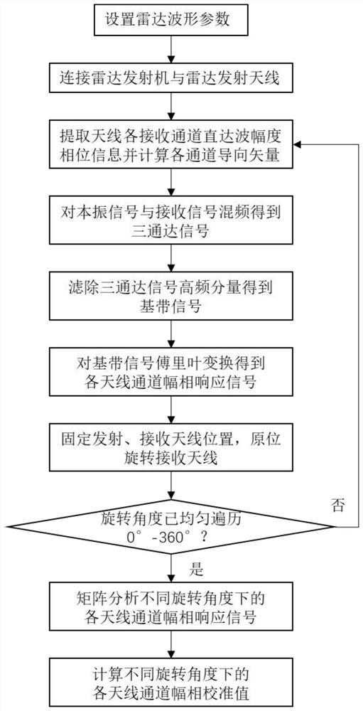
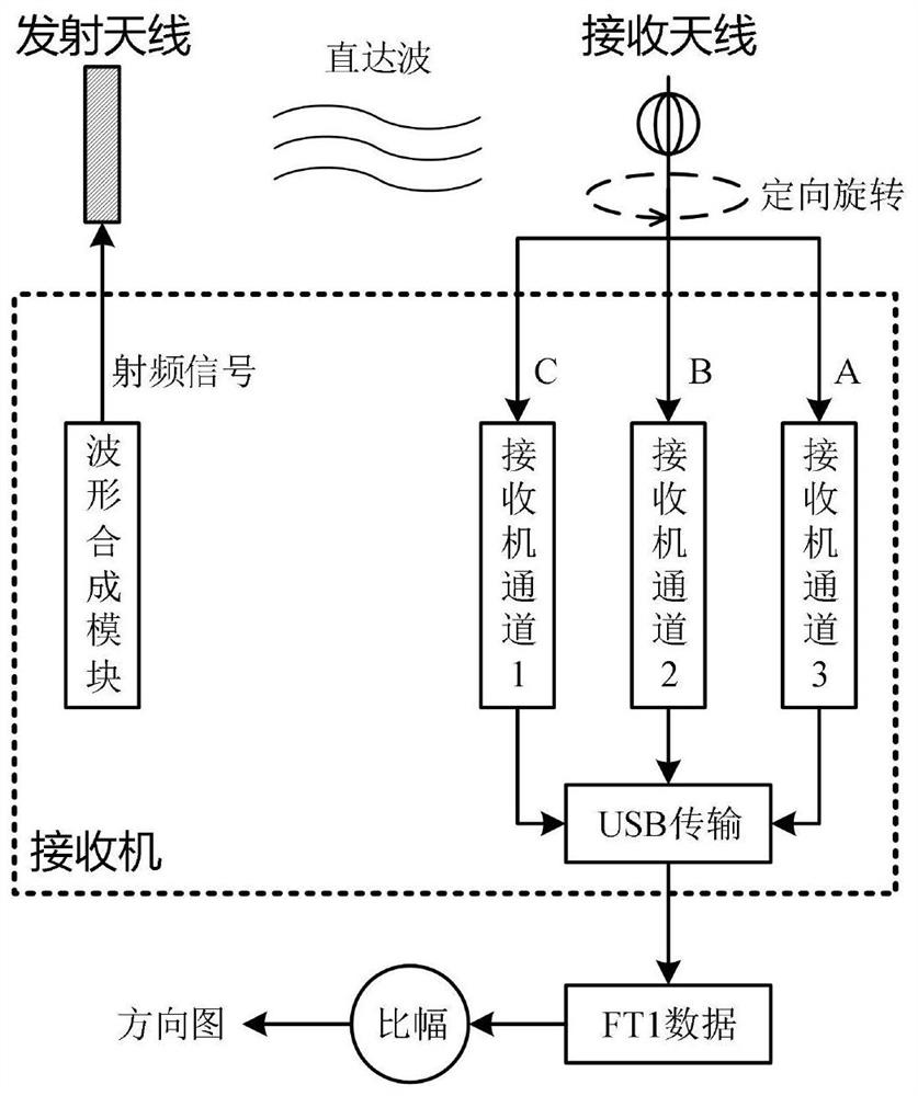
[0096] figure 2 Overall block diagram for radar receiver channel calibration. During the channel calibration process, keep the positions of the transmitting and receiving antennas unchanged, and perform calibration according to the following steps:

[0097] 1) Initialize settings. Adjust the normal direction of the receiving antenna so that it points to the transmitting antenna; reduce the transmitting power by about 50dB (the specific value is appropriate to ensure that the direct wave signal is within the dynamic range of the receiver, or directly connect the signal at the input end of the power amplifier to the transmitting antenna), At the same time, modify the radar waveform parameters so that the transmit and receive windows partially overlap (the overlapping pulse width is not strictly required); under the condition of keeping the frequency of the transmit signal unchanged, modify the frequency of the received local oscillator signal so that there is a certain frequency


PUM


Abstract

The invention discloses a radar receiving channel calibration method based on a monopole crossed loop antenna. Aiming at a radar system which takes a monopole crossed loop antenna as a receiving sensor, the rapid calibration of the amplitude and phase response of each receiving channel is completed under the conditions that the hardware structure and the installation mode of the system are not changed and an external signal source is not used. The basic idea of the method is that a closed loop is formed by using a transmitting antenna, a receiving antenna and a radar receiver which are fixed in position, frequency difference simulation delay between transmitting and receiving local oscillator signals is set, and the amplitude-phase response of each receiving channel is calculated through equivalent matched filtering processing; the included angle between the receiving antenna and the transmitting antenna is changed by rotating the receiving antenna, an amplitude-phase response result within the range of 360 degrees is obtained and compared with an ideal value, and finally the inherent amplitude-phase difference of each receiving channel is obtained. The method does not depend on an external auxiliary signal source, does not need to change a radar system, can eliminate the influence of the external environment of the antenna on a measurement result, and is an effective means for detecting the characteristic difference of radar receiving channels.

Description


Claims


Application Information

Patent Timeline
Owner WUHAN UNIV
Why Eureka
Try Eureka