Valve unblocking device

A technology of blocking and valve, applied in cleaning methods and utensils, cleaning hollow objects, chemical instruments and methods, etc., can solve problems such as corrosion, low cleaning efficiency, poisoning, etc., to ensure personal safety and facilitate the cleaning of blockages. Effect

Active Publication Date: 2022-06-03
中国石化海南炼油化工有限公司
View PDF9 Cites 0 Cited by
  • Summary
  • Abstract
  • Description
  • Claims
  • Application Information

AI Technical Summary

Benefits of technology

This technology allows the driver part of the device to move backward when there's no wastewater being drained from its drain portions without causing any problems or harming operators who may come into contact with them during operation.

Problems solved by technology

This patented technical problem addressed by this patents relates to finding better ways for draining petroleum products from tanks without causing damage or injury caused by metal tools used while doing maintenance work on them.

Method used


Image

  • Valve unblocking device
  • Valve unblocking device
  • Valve unblocking device

Examples


Embodiment Construction

[0039] In order to make the purposes, technical solutions and advantages of the embodiments of the present invention clearer, the technical solutions in the embodiments will be clearly and completely described below with reference to the drawings in the embodiments of the present invention, and the following embodiments are used to illustrate the present invention , but are not intended to limit the scope of the present invention.

[0040] In the description of the present invention, it should be noted that the terms "upper", "lower", "front", "rear", "left", "right", "vertical", "inner", "outer", etc. The indicated orientation or positional relationship is based on the orientation or positional relationship shown in the accompanying drawings, which is only for the convenience of describing the present invention and simplifying the description, rather than indicating or implying that the indicated device or element must have a specific orientation or a specific orientation. const


PUM


Abstract

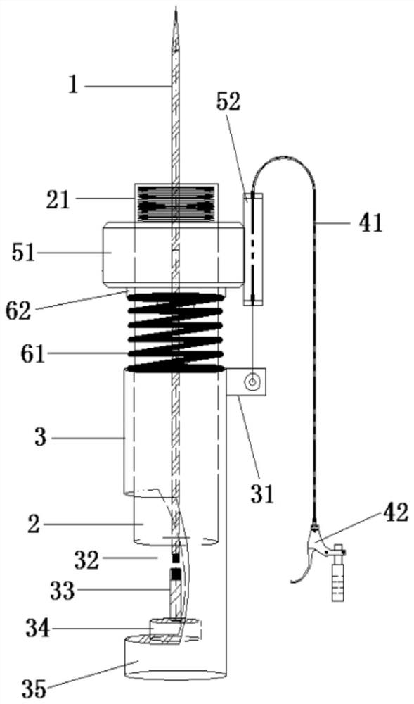
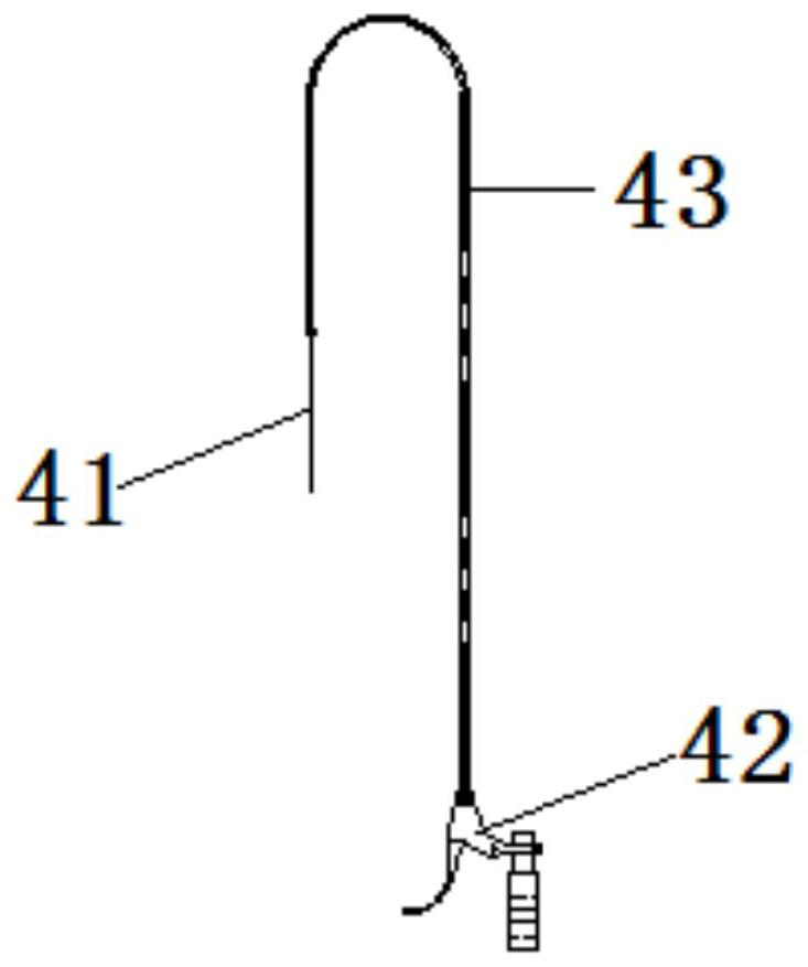
The invention relates to the field of unblocking equipment, and discloses a valve unblocking device which comprises a main pipe body, and the main pipe body is provided with a connecting part used for being connected with a to-be-unblocked valve and an unblocking cavity allowing blockages in the to-be-unblocked valve to pass through. The guide pipe is provided with a blockage dredging needle penetrating through the blockage dredging cavity, the guide pipe can reciprocate relative to the main pipe body in the axial direction of the main pipe body so as to drive the blockage dredging needle to dredge the valve to be dredged, and the guide pipe and/or the main pipe body are/is provided with a sewage discharging part communicated with the blockage dredging cavity; and the driving part is arranged to be capable of being operated on the side opposite to the forming direction of the pollution discharge part so as to drive the guide pipe in the axial direction of the main pipe body. The driving part is arranged to be capable of being controlled on the side opposite to the opening direction of the sewage discharging part, and the guided blockages cannot be splashed to the body of an operator, so that the operator can conveniently clean the blockages, and the personal safety of the operator can be guaranteed.

Description


Claims


Application Information

Patent Timeline
Owner 中国石化海南炼油化工有限公司
Why Eureka
Try Eureka