Beam body embedded part inspection system and method

An inspection system and inspection method technology, applied in the field of beam body embedded parts inspection system field, can solve the problems of large precision error of embedded parts detection, force influence of beam body structure, and difficulty of beam body reinforcement into molds, etc. The effect of improving measurement efficiency, improving measurement accuracy and accuracy

Pending Publication Date: 2022-06-14
北京好运达智创科技有限公司
View PDF0 Cites 0 Cited by
  • Summary
  • Abstract
  • Description
  • Claims
  • Application Information

AI Technical Summary

Benefits of technology

This invention describes an apparatus that checks if there're any cracks or defects inside bolts during manufacturing processes. It uses images from cameras attached to the machine tool itself to calculate their position relative to other components like cables or pipes. By comparing these positions with those found beforehand, it becomes possible to identify issues such as cracking or misalignment caused by factors like temperature changes or vibrations.

Problems solved by technology

This patented technical problem addressed by this patents relates to improving the precision with detecting hidden partings during manufacturing processes used to create boxes or girders that require embedding reinforcement material (such as bolts) inside their walls. Existing methods rely heavily upon human judgment and may result in errors when manually inspecting these areas without proper training.

Method used


Image

  • Beam body embedded part inspection system and method

Examples


Embodiment Construction

[0021] The technical solutions of the present invention will be clearly and completely described below with reference to the accompanying drawings. Obviously, the described embodiments are part of the embodiments of the present invention, but not all of the embodiments. Based on the embodiments of the present invention, all other embodiments obtained by those of ordinary skill in the art without creative efforts shall fall within the protection scope of the present invention.

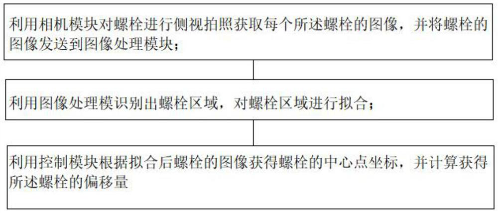
[0022] An embodiment of the present invention provides an inspection system for beam embedded parts, wherein the embedded parts include a base plate and bolts, the base plate is provided with a plurality of bolt holes, and the bolts are respectively installed in each of the bolt holes. A plating layer is provided on the surface of the bottom plate. The system includes an inspection platform for placing embedded parts, and a camera module, an image processing module and a control module arranged on one side


PUM


Abstract

The invention discloses a beam body embedded part inspection system and method.The beam body embedded part inspection system comprises a detection platform used for containing an embedded part, a camera module, an image processing module and a control module, the camera module, the image processing module and the control module are arranged on one side of the detection platform, the embedded part comprises a bottom plate and bolts, and a plurality of bolt holes are formed in the bottom plate; the bolts are installed in the bolt holes respectively, and a plating layer is arranged on the surface of the bottom plate. Wherein the camera module is used for carrying out side view photographing on bolts to obtain an image of each bolt, and sending the images of the bolts to the image processing module; the image processing module is used for identifying a bolt area and fitting the bolt area; and the control module is used for obtaining the center point coordinate of the bolt according to the fitted image of the bolt and calculating the offset of the bolt. Through the method, the perpendicularity condition of the bolt can be judged, so that whether the perpendicularity of the bolt meets related requirements or not is judged.

Description


Claims


Application Information

Patent Timeline
Owner 北京好运达智创科技有限公司
Why Eureka
Try Eureka