Green light steel keel partition wall building material production bending equipment
A light steel keel and building material technology, applied in metal processing equipment, storage devices, feeding devices, etc., can solve problems such as low efficiency and achieve high efficiency
- Summary
- Abstract
- Description
- Claims
- Application Information
AI Technical Summary
Benefits of technology
Problems solved by technology
Method used
Image

Examples
Embodiment 1
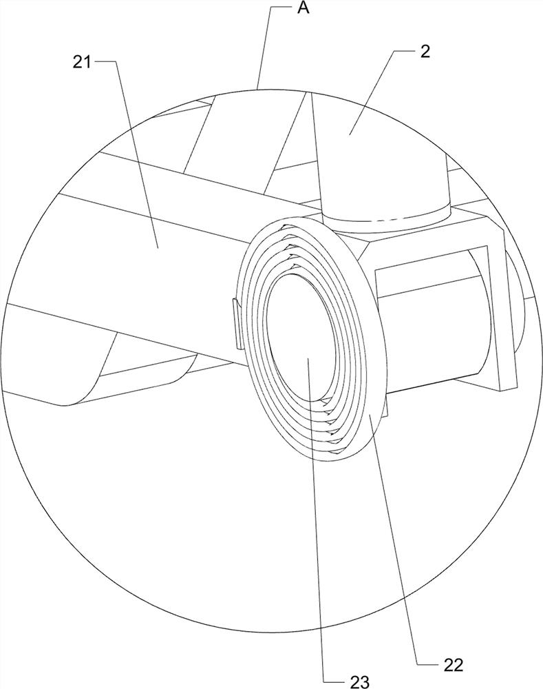
[0035] A green light steel keel partition wall building material production and bending equipment, including a support frame 1, a hydraulic cylinder 2, a fixed block 21, a first scroll spring 22, an installation column 23, a pressure block 3, an installation frame 31, and a positioning mechanism 4 and limit mechanism 5, see Figure 1-Figure 6 As shown, a fixing block 21 is installed in the middle of the lower part of the outer right side of the support frame 1 by welding, the right end of the fixing block 21 is rotatably connected with a mounting column 23, and a hydraulic cylinder is installed on the mounting column 23 by welding. 2. The end of the telescopic rod of the hydraulic cylinder 2 is fixed with a pressure block 3. When the pressure block 3 moves upward, the pressure block 3 can bend the light steel keel. The front side of the installation column 23 and the right side of the front side of the fixed block 21 A first scroll spring 22 is connected between them, a mounting
Embodiment 2
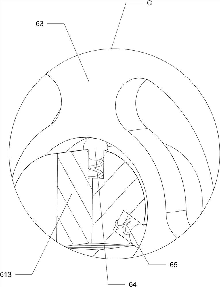
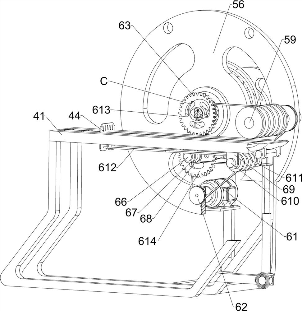
[0042] On the basis of Embodiment 1, a feeding mechanism 6 is also included. The feeding mechanism 6 includes a servo motor 61, a V-belt assembly 62, a spur gear 63, a friction ball 64, a fourth spring 65, a rotating rod 66, and a fixed plate. 67. Transmission assembly 68, mounting plate 69, mounting rod 610, reel 611, pull wire 612, guide shaft 613 and rotating gear 614, please refer to figure 1 , figure 2 , Figure 4 , Figure 7 and Figure 8 As shown, the right side of the outer bottom of the mounting frame 41 is symmetrically installed with a mounting plate 69 by welding, and a mounting rod 610 is rotatably penetrated between the lower parts of the mounting plates 69 on the front and rear sides. The fixed sleeve is provided with a winding wheel 611, and a pull wire 612 is wound on the winding wheel 611. The tail ends of the two pull wires 612 are fixedly connected to the lower part of the right side of the push plate 44. When the pull wire 612 is wound, the pull wire 612
Embodiment 3
[0047] On the basis of Embodiment 1 and Embodiment 2, a material receiving mechanism 8 is also included. The material receiving mechanism 8 includes a guide frame 81 and a sponge plate 82. Please refer to figure 1 , figure 2 and Figure 12 As shown in the figure, a guide frame 81 is installed on the upper part of the outer right side of the support frame 1 symmetrically through welding, and a sponge plate 82 is fixed between the inner side and the right side of the guide frame 81 on the front and rear sides. When the keel falls onto the sponge plate 82, the sponge plate 82 can buffer the bent light steel keel.
[0048] Also includes an adsorption mechanism 9, the adsorption mechanism 9 includes a fixed frame 91 and a magnetic block 92, please refer to figure 1 , figure 2 and Figure 13 As shown, a fixing frame 91 is installed on the upper part of the inner and rear sides of the mounting frame 31 by welding, the fixing column 51 passes through the middle of the fixing frame
PUM
 Abstract
Description
Claims
Application Information
 - R&D Engineer
- R&D Manager
- IP Professional
- Industry Leading Data Capabilities
- Powerful AI technology
- Patent DNA Extraction
Browse by: Latest US Patents, China's latest patents, Technical Efficacy Thesaurus, Application Domain, Technology Topic.
© 2024 PatSnap. All rights reserved.Legal|Privacy policy|Modern Slavery Act Transparency Statement|Sitemap