Negative pressure elevator car with air disinfecting and filtering functions
- Summary
- Abstract
- Description
- Claims
- Application Information
AI Technical Summary
Benefits of technology
Problems solved by technology
Method used
Image

Examples
Embodiment 1
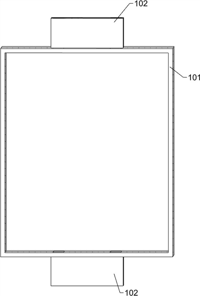
[0032] A negative pressure elevator car with air disinfection and filtration function, such as Figure 1-Figure 12 As shown, it includes an elevator car 101, a negative pressure box 102, a negative pressure air exchange mechanism, an air filter mechanism and an air inlet and outlet control mechanism. The upper and lower sides of the elevator car 101 are fixedly connected with a negative pressure box 102. The two negative pressure boxes 102 are arranged symmetrically up and down, and a negative pressure air exchange mechanism is fixed in the two negative pressure boxes 102. The negative pressure air exchange mechanism is used to exchange the air in the elevator car 101 and the elevator shaft. The pressure box body 102 is fixed with an air filter mechanism. The two air filter mechanisms are respectively located inside the two negative pressure air exchange mechanisms. The air filter mechanism is used to filter air. The channel control mechanism, the inlet and outlet channel control
Embodiment 2
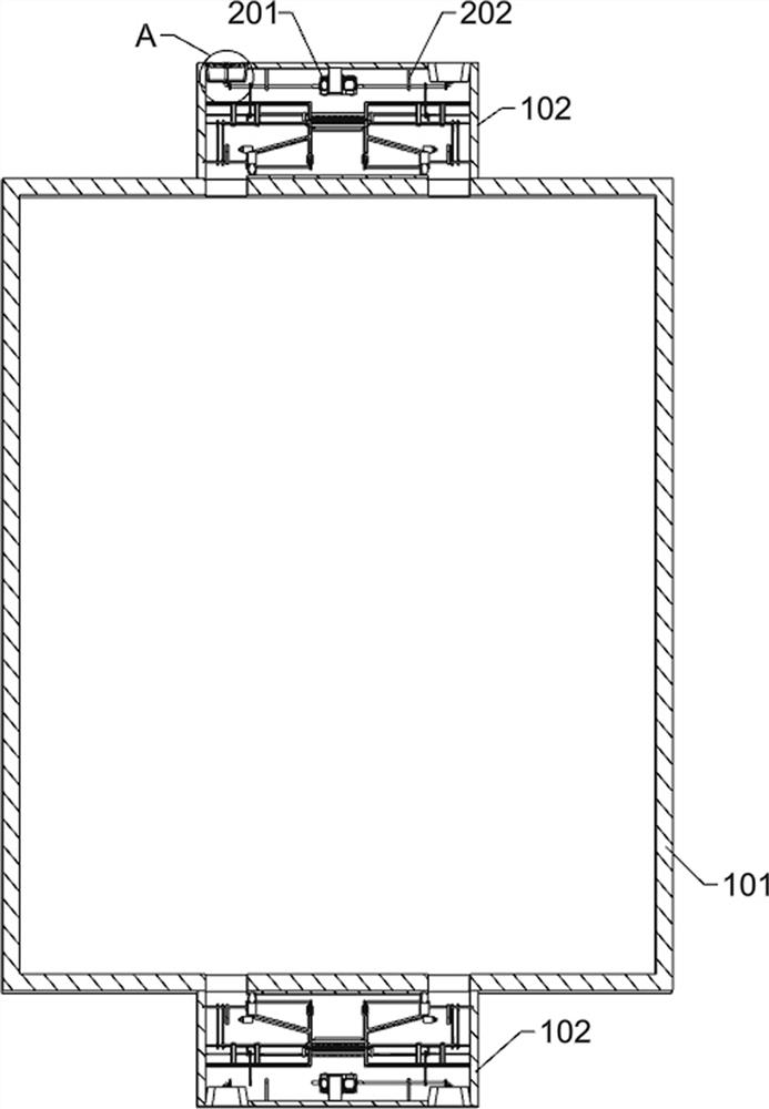
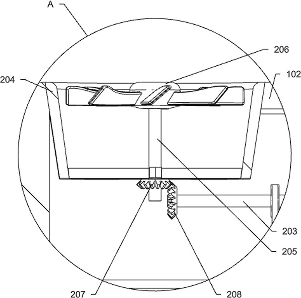
[0036] On the basis of Example 1, as figure 2 and image 3 As shown, the negative pressure air exchange mechanism includes a biaxial motor 201, a first fixing frame 202, a first rotating rod 203, a fan casing 204, a second rotating rod 205, a turbofan 206, a first bevel gear 207 and a second The bevel gear 208, the biaxial motor 201 is fixed to the inner upper side of the negative pressure box 102 through the connecting block, there are two first fixing frames 202, and the two first fixing frames 202 are fixed to the negative pressure box. On the inner upper side of the body 102, the two first fixing frames 202 are located on the left and right sides of the biaxial motor 201. The left and right ends of the output shaft of the biaxial motor 201 are fixed with a first rotating rod 203, and the two first rotating rods 203 They are respectively rotatably connected to the two first fixing frames 202, and the two first rotating rods 203 are respectively rotatably connected to the lef
Embodiment 3
[0058] On the basis of Example 2, as Figure 13 As shown, it also includes an air sterilization mechanism, the air sterilization mechanism includes a second reciprocating screw 501, a third fixed rod 502, an air sterilization extrusion block 503 and an air sterilant watering can 504, a second bracket 302 and a negative pressure box A second reciprocating screw 501 is rotatably connected between the 102, and two third fixing rods 502 are fixedly connected between the second bracket 302 and the negative pressure box 102, and the two third fixing rods 502 are respectively located on the second reciprocating screw. On the left and right sides of 501, the air disinfection extrusion block 503 is threadedly connected to the second reciprocating screw 501, the air disinfection extrusion block 503 is slidably connected to the two third fixing rods 502, and the air disinfectant watering can 504 is fixed to the second bracket. On the left side of 302, an air sanitizer spray can 504 is used
PUM
 Abstract
Description
Claims
Application Information
 - R&D Engineer
- R&D Manager
- IP Professional
- Industry Leading Data Capabilities
- Powerful AI technology
- Patent DNA Extraction
Browse by: Latest US Patents, China's latest patents, Technical Efficacy Thesaurus, Application Domain, Technology Topic.
© 2024 PatSnap. All rights reserved.Legal|Privacy policy|Modern Slavery Act Transparency Statement|Sitemap