Control method and control device of magnetic resonance system

A control method and magnetic resonance technology, which are applied in the direction of using nuclear magnetic resonance imaging system for measurement, magnetic resonance measurement, measurement device, etc., can solve the problems of expected field strength change of radio frequency field strength, affecting imaging effect, etc., to improve accuracy and reliability. speed, reduced impact, reduced noise error effect

Pending Publication Date: 2022-08-02
UNITED IMAGING RES INST OF INNOVATIVE MEDICAL EQUIP
View PDF7 Cites 0 Cited by
  • Summary
  • Abstract
  • Description
  • Claims
  • Application Information

AI Technical Summary

Benefits of technology

The technical solution described in this patented technology allows for precise adjustment of the intensity (RF) pulses used during MRI scans without being influenced by external influences like temperature or pressure variations. This results in improved image quality while maintaining consistently high-quality images captured under varying conditions over time.

Problems solved by technology

This patented technical problem addressed in this patents relates to improving image quality when an MRI scanner operates with different types of objects like humans' bodies during MR angiography procedures. These variations can cause issues for accurate results because they result in changes made on the signal intensity at specific locations within the subject being imaged. Prior methods have resulted in suboptimal solutions which require iterative calculations over many samples before obtaining the best estimate.

Method used


Image

  • Control method and control device of magnetic resonance system
  • Control method and control device of magnetic resonance system

Examples


Embodiment Construction

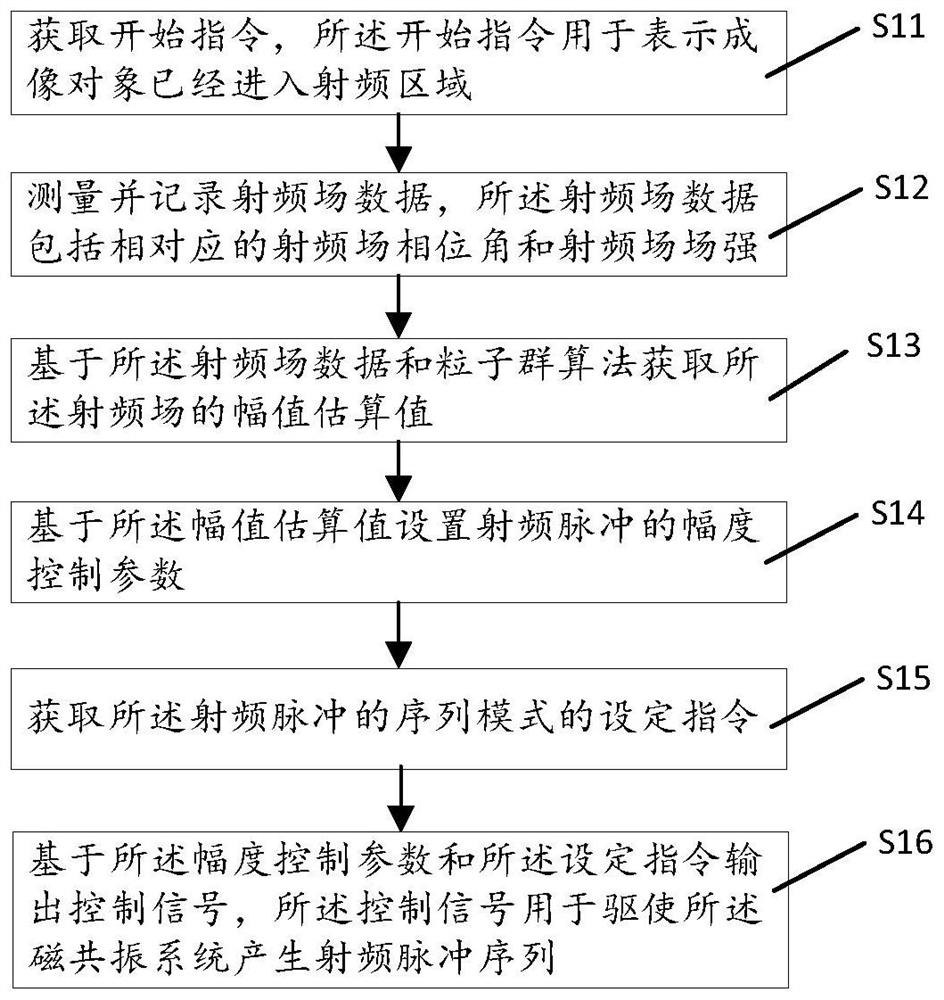
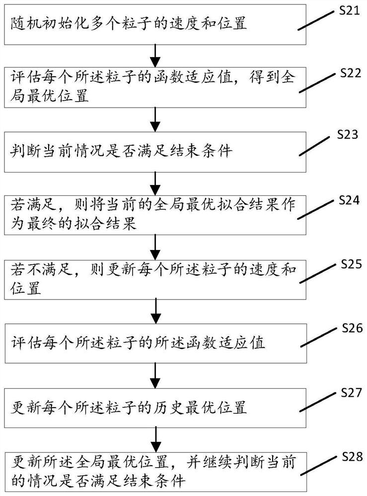
[0021] In order to make the objects, advantages and features of the present invention clearer, the present invention will be further described in detail below with reference to the accompanying drawings and specific embodiments. It should be noted that the accompanying drawings are all in a very simplified form and are not drawn to scale, and are only used to facilitate and clearly assist the purpose of explaining the embodiments of the present invention. Furthermore, the structures shown in the drawings are often part of the actual structure. In particular, each drawing needs to show different emphases, and sometimes different scales are used.

[0022] As used herein, the singular forms "a," "an," and "the" include plural referents, the term "or" is generally employed in its sense including "and / or", and the term "a number" It is usually used in the sense including "at least one", the term "at least two" is usually used in the sense including "two or more", in addition, the t


PUM


Abstract

The invention provides a control method and a control device of a magnetic resonance system. The control method comprises the following steps: measuring and recording radio frequency field data; obtaining an amplitude estimation value of the radio frequency field based on the radio frequency field data and a particle swarm algorithm; setting an amplitude control parameter of the radio frequency pulse based on the amplitude estimation value; acquiring a setting instruction of the sequence mode of the radio frequency pulse; and outputting a control signal based on the amplitude control parameter and the setting instruction. According to the configuration, on one hand, actual data of the radio frequency field can be found through measurement, on the other hand, the amplitude estimation value of the radio frequency field can be obtained based on the particle swarm optimization, the influence of noise errors is reduced, and the radio frequency amplitude calibration precision and speed are improved. Therefore, the problem that in the prior art, due to the fact that the field intensity of the radio frequency field is affected by various factors, the expected field intensity is changed, and the imaging effect is affected is solved.

Description


Claims


Application Information

Patent Timeline
Owner UNITED IMAGING RES INST OF INNOVATIVE MEDICAL EQUIP
Why Eureka
Try Eureka