Method for making a non-contact smart card with an antenna support made of fibrous material

A manufacturing method and technology for smart cards, which are applied to record carriers, printed matter, instruments, etc. used by machines, and can solve the problems of fraud, high cost, and inability to produce

Inactive Publication Date: 2005-07-20
ASK CORP
View PDF0 Cites 0 Cited by
  • Summary
  • Abstract
  • Description
  • Claims
  • Application Information

AI Technical Summary

Problems solved by technology

While this does not prevent the card from working correctly, this flaw is often highlighted by users who care a lot about aesthetics
[0012] In addition, the cost of manufacturing the card with such a process is too high for a

Method used


Image

  • Method for making a non-contact smart card with an antenna support made of fibrous material
  • Method for making a non-contact smart card with an antenna support made of fibrous material
  • Method for making a non-contact smart card with an antenna support made of fibrous material

Examples


manufacture example

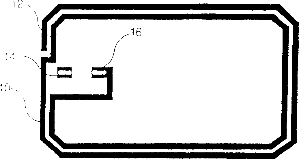
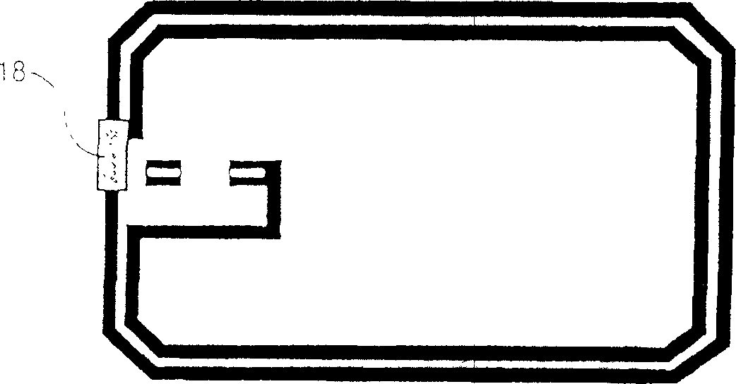
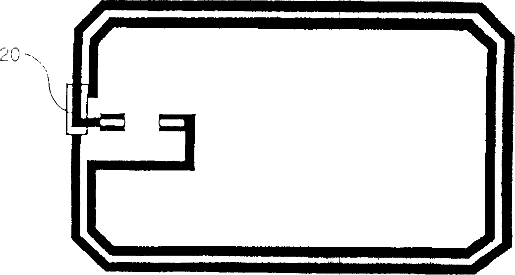
[0023] Lamination is achieved by thermoforming. According to a preferred embodiment, two layers of plastic material are used for each card body. This plastic material is typically polyvinyl chloride (PVC), polyester (PET, PETG), polycarbonate (PC), or acrylonitrile-butadiene-styrene (ABS). According to a preferred embodiment, PVC is used. The two layers have different stiffnesses. The outer layer is made of hard PVC and the inner layer (the layer in contact with the antenna support) is made of PVC with a low Vicat softening temperature (this is the temperature at which PVC transitions from an air-hard state to a rubber state). Made of soft PVC. The two layers may also have different thicknesses. For example, each card body includes an outer hard PVC layer with a thickness of about 310 microns (μm), and an inner soft PVC layer with a thickness of about 80 μm. The antenna support is made of paper with a thickness of about 125 μm. According to another manufacturing example, wh


PUM


Abstract

The present invention relates to a contactless smart card manufacturing process and more specifically to a manufacturing process for a contactless smart card for which the antenna is on a fibrous material such as paper. This process includes a manufacturing step to screen print the antenna onto the support, a step to bond the contacts of the chip onto the antenna support using conductive glue, and a step designed to laminate the card body onto the antenna support by hot press molding. Cutouts made in the corners of the antenna support prior to the lamination step enable the card bodies to be bonded together. The card thus obtained allows a posteriori viewing of any mechanical misuse to which it may have been subjected (extreme bending).

Description


Claims


Application Information

Patent Timeline
Owner ASK CORP
Why Eureka
Try Eureka