Balancing weight unit of ring spindle spinning frame

A technology of a balancing device and a spinning frame, which is applied to spinning machines, continuously wound spinning machines, textiles and papermaking, etc., can solve the problems of complex structure of the balancing device, inconvenient maintenance, easy fatigue of torsion bars and damage to the balancing effect, etc. , to achieve the effect of simple structure, reliable performance and simplified balance mechanism

Inactive Publication Date: 2002-07-31
BEST MACHINE BUILDING YUCI DEVPT ZONE
View PDF0 Cites 7 Cited by
  • Summary
  • Abstract
  • Description
  • Claims
  • Application Information

AI Technical Summary

Benefits of technology

This new design uses an improved weigh balancing system that overcomes problems associated with traditional methods such as tension bars or rods used for longer periods of time due to their weaknesses. It provides better stability without being easily damaged by external forces like vibrations or impacting objects during normal usage conditions. Additionally, this design makes it easier to maintain and improve its overall function while reducing production cost and machinery expenses.

Problems solved by technology

Technically speaking, there exist two types of existing methods in use today's rings spinnerets that have an equal amount of force on both sides when rotating at different speeds or directions. These systems require complicated structures with multiple components such as springs and bending bars which may wear out over time due to constant changes made by these devices during operation. Additionally, they often result in imbalances between upstream and down stream rollers causing unequal pressure levels across them.

Method used


Image

  • Balancing weight unit of ring spindle spinning frame
  • Balancing weight unit of ring spindle spinning frame

Examples


Embodiment Construction

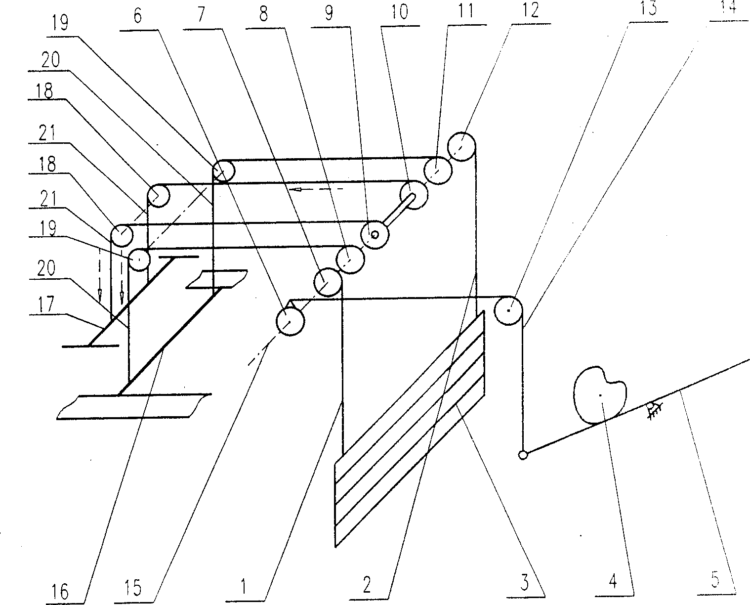
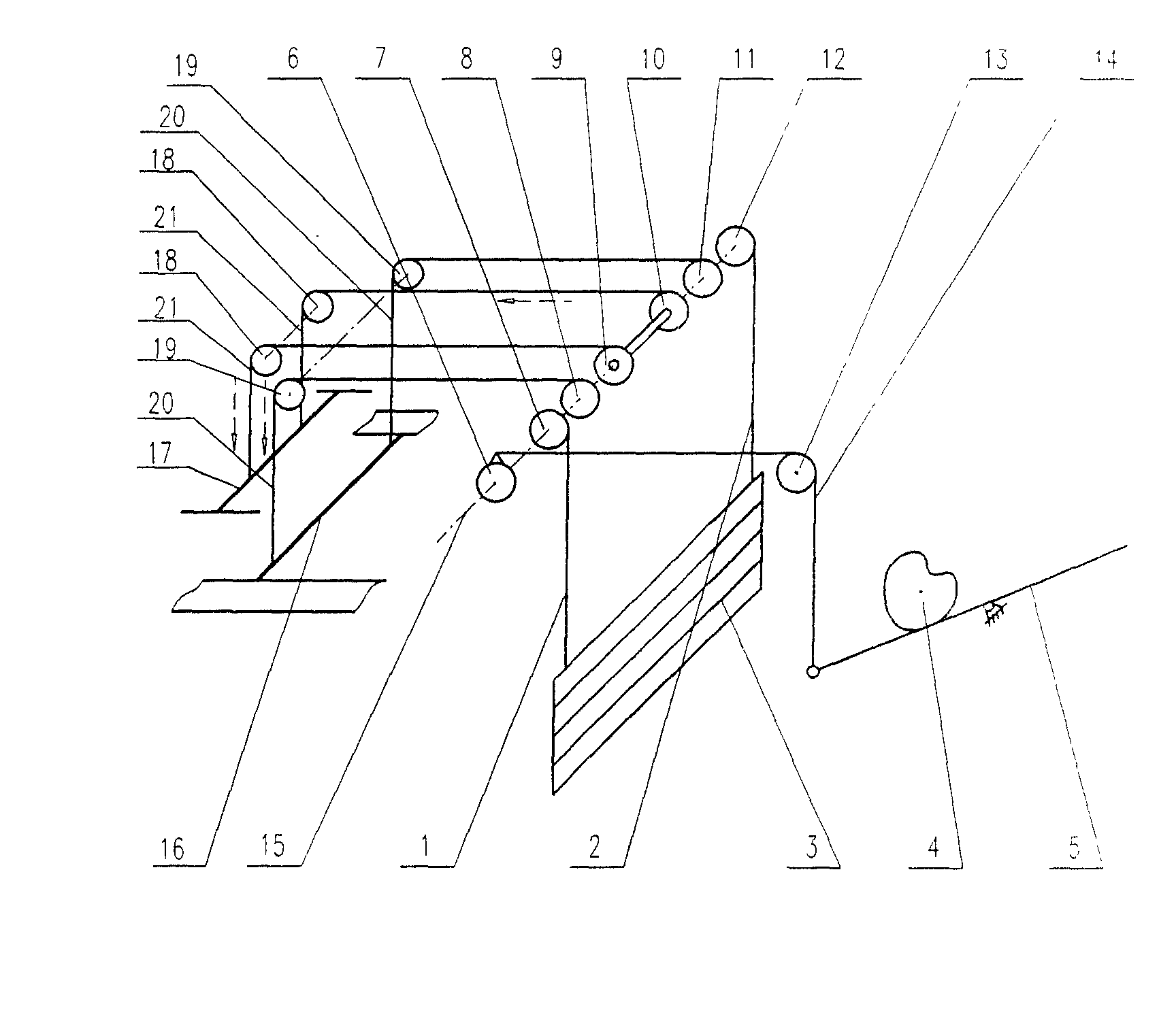
[0008] The present invention will be further described below in conjunction with the accompanying drawings and embodiments.

[0009] As shown in the accompanying drawings, the weight balance device of the ring spinning frame in this embodiment includes a fixed sprocket 13, a forming cam 4, a swing arm 5 in contact with the forming cam 4, and the end of the swing arm 5. The leading chain 14 that is connected and the driving mechanism that the main sprocket 6 that is connected with main driving chain 14 constitutes, is connected with driven sprocket 8,9,10,11 by driven sprocket 8,9,10,11 Lifting chain 20,21, the lifting member 16,17 that is connected with the other end of lifting chain 20,21 and the hoisting mechanism that transition sprocket wheel 18,19 constitutes. Among them, it also includes a weight balance mechanism composed of two transmission sprockets 7, 12, traction chains 1, 2, 4 counterweights 3 and an upper distribution shaft 15. The two transmission sprockets 7, 12 ar


PUM


Abstract

The balancing weight unit of ring spindle spinning frame includes a dragging mechanism comprising fixed chain wheel, forming cam, oscillating arm, main dragging chain and main chain wheel; an elevating mechanism comprising driven chain wheel, elevating chain, elevating part and transition chain wheel; and a balancing weight mechanism comprising two transmissino chain wheels, suspending chain, balancing weight and upper distribution shaft. The two transmission chain wheels are connected through the suspending chain to the balancing weight; and the main chain wheel, the two transmission chain wheels and the driven chain wheel are set successively on the upper distribution shaft for elevation motion.

Description


Claims


Application Information

Patent Timeline
Owner BEST MACHINE BUILDING YUCI DEVPT ZONE
Why Eureka
Try Eureka