Fluorescence detecting system for quantitative gene magnification instrument

A technology for fluorescence detection and gene amplification, applied in the field of fluorescence detection systems, can solve the problems of complex metals, large scattering and attenuation of light intensity, and high cost, and achieve the effects of reducing manufacturing costs and improving detection sensitivity.

Inactive Publication Date: 2003-06-11
SUZHOU MOLARRAY CO LTD +1
View PDF0 Cites 5 Cited by
  • Summary
  • Abstract
  • Description
  • Claims
  • Application Information

AI Technical Summary

Problems solved by technology

At the same time, due to the complexity of metals that receive fluorescence from the upper part of the base, the fluorescence will scatter and atten

Method used


Image

  • Fluorescence detecting system for quantitative gene magnification instrument
  • Fluorescence detecting system for quantitative gene magnification instrument
  • Fluorescence detecting system for quantitative gene magnification instrument

Examples


Embodiment Construction

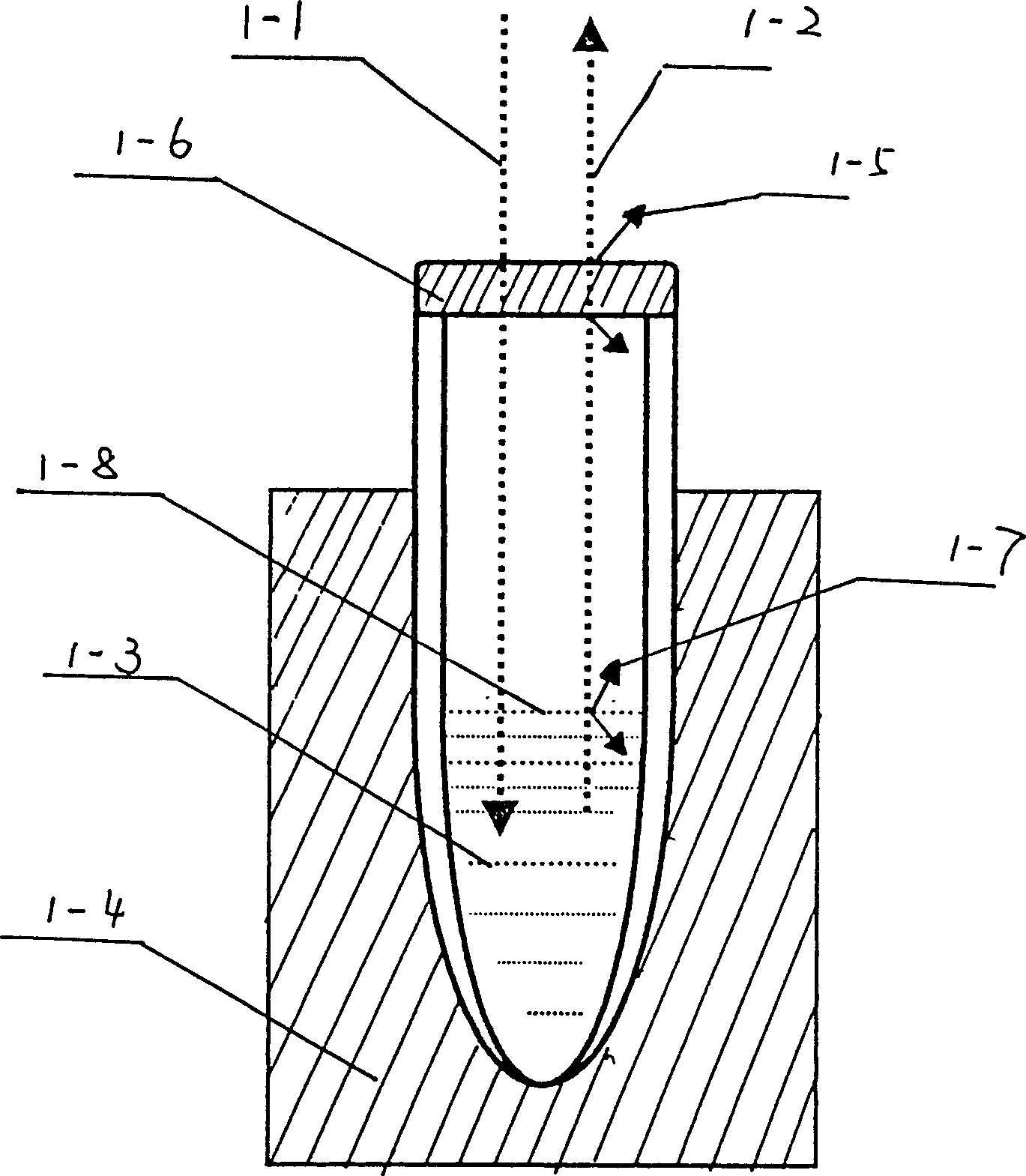
[0010] Quantitative gene amplification instruments are generally composed of a fluorescence detection system, a data processing system and a display system. The fluorescence detection systems of the existing quantitative gene amplification instruments are such as figure 1 1-1 is the excitation light, 1-2 is the fluorescence emission, 1-3 is the sample, 1-4 is the sample base, 1-5 is the cap scattered light, 1-6 is the cap, 1- 7 is the liquid surface scattered light, 1-8 is the sample liquid level. When the excitation light is reflected by the sample and reaches the interface 1-8 between the sample liquid and the air, part of the light scattering 1-7 occurs, and then when the reflected light reaches the cap 1-6, light scattering 1-5 occurs again, thus The intensity of light is greatly weakened, which affects the sensitivity of detection.

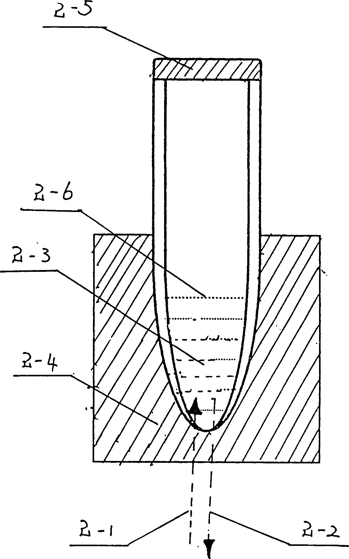
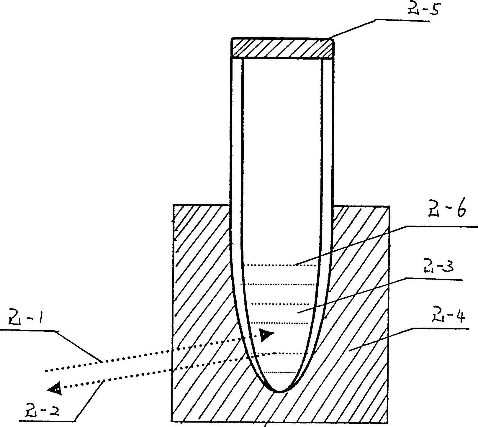
[0011] The quantitative gene amplification instrument of the present invention is also composed of a fluorescence detection system, a data pro


PUM


Abstract

The fluoroscopic examination system of quantitative gene augmentor is composed of the light source with the color filter, the two-way mirror positioned in front of the light source inclined 45 degrees, the 96 optical fiber bundle coaxial with the light source and the corresponding sample cells. Each optical fiber bundle is leaded in the pinhole in the bottom of the base in each sample cell. The excitation and the reception of fluorescence are realized directly on the wall of the reaction tube. Thus, the phenomena of the fluorescence scattering and the light intensity attenuation are eliminated. The invention raises the detection sensitivity and reduces the manufacturing cost so as to possess the application value.

Description


Claims


Application Information

Patent Timeline
Owner SUZHOU MOLARRAY CO LTD
Why Eureka
Try Eureka