Open loop variable gain amplifier using replica gain cell and signal amplification method

A technology of gain amplifier and gain control signal, which is applied in the direction of DC coupled DC amplifier, amplifier, amplifier with semiconductor device/discharge tube, etc.

Inactive Publication Date: 2010-05-26
INFINEON TECH AG
View PDF4 Cites 0 Cited by
  • Summary
  • Abstract
  • Description
  • Claims
  • Application Information

AI Technical Summary

Problems solved by technology

This further limits the application of VGAs with s

Method used


Image

  • Open loop variable gain amplifier using replica gain cell and signal amplification method
  • Open loop variable gain amplifier using replica gain cell and signal amplification method
  • Open loop variable gain amplifier using replica gain cell and signal amplification method

Examples


Embodiment Construction

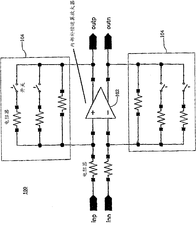
[0017] One of the most critical factors in the design of fast signal processing systems is the combined bandwidth of all components in the signal path, resulting signal distortion, and loss of signal strength. The signal path is defined as the path, ie the circuit and connections, the input signal is processed, ie amplified to the output, which is the signal passed to a subsequent processing / circuit stage. Two forms of variable gain amplifier (VGA) structures are generally available, closed loop and open loop, for incorporation into such signal processing systems. Closed loop maintains signal gain and circuit stability through a feedback loop in the signal path that recirculates the amplified output signal, typically through an operational amplifier and resistor network. Open-loop VGAs, on the other hand, do not impose a feedback loop in the signal path, but rely only on externally generated signals to adjust signal gain and circuit stability.

[0018] figure 1 A closed-loop


PUM


Abstract

A variable gain amplifier ('VGA') having an open loop architecture is disclosed. The VGA includes one or more gain cells coupled in the signal path to amplify a given input signal. The VGA further includes a replica gain cell having a gain servo circuit which amplifies a gain reference signal according to a programmable gain input and equalizes the amplified reference signal to the original unamplified reference signal, continuously generating a gain control input to the signal path gain cells based on the equalization. This gain control input reflects the gain set by the programmable gain input as adjusted for process, temperature and supply voltage variations. The replica gain cell further includes a common mode voltage servo circuit which senses the common mode voltage of the amplifiedreference signal and equalizes it to a common mode voltage reference, generating a common mode voltage control signal to the signal path gain cells to regulate their common mode voltage. This regulation of the common mode voltage of the signal path gain cells is compensated for process, temperature and supply voltage variations.

Description


Claims


Application Information

Patent Timeline
Owner INFINEON TECH AG
Why Eureka
Try Eureka